Light-emitting diode (LED) illumination module

A technology of LED lighting and LED light source, which is applied in the field of optics, can solve the problems of not meeting the requirements of light distribution and single light distribution effect, and achieve the effect of improving utilization rate and uniform light spot

Active Publication Date: 2012-10-17
SHENZHEN LANGHENG ELECTRICAL
View PDF10 Cites 20 Cited by
  • Summary
  • Abstract
  • Description
  • Claims
  • Application Information

AI Technical Summary

Problems solved by technology

However, the light distribution effect of this lens structure is single, which cannot meet various light distribution requirements.

Method used


Image

  • Light-emitting diode (LED) illumination module
  • Light-emitting diode (LED) illumination module
  • Light-emitting diode (LED) illumination module

Examples


Embodiment Construction

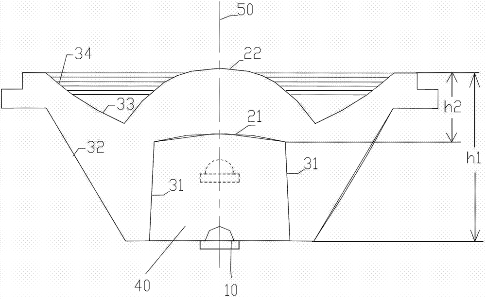
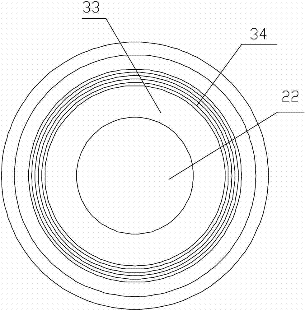
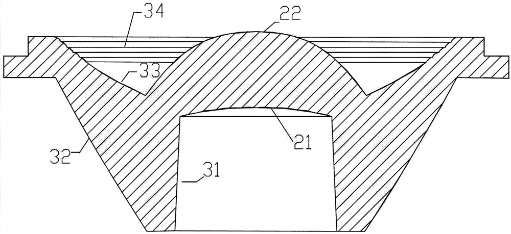
[0028] The LED lighting module structure of the preferred embodiment of the present invention is as follows: figure 1 , figure 2 , image 3 shown, see also Figure 4 and Figure 5 , the LED lighting module includes an LED light source 10 and a rotationally symmetrical single-piece light-transmitting auxiliary optical structure. The light-transmitting auxiliary optical structure is a secondary optical system, including a flood lens group 20 located in the middle, a reflective lens group 30 located around, and a blind hole-shaped opening 40 located on the back, where the LED light source 10 is disposed. Wherein, the opening 40 includes a concave curved base surface 21 and a tapered circumferential surface 31, and the opening 40 has a circumferential diameter that allows the LED light source 10 to move relatively along the optical axis 50 of the light-transmitting auxiliary optical structure; the flood lens group 20 includes as The base surface 21 of the light incident surfa...


PUM


Abstract

The invention relates to a light-emitting diode (LED) illumination module. The LED illumination module comprises an LED light source and a rotational symmetric single light-transmitting auxiliary optical structure, wherein the light-transmitting auxiliary optical structure comprises a flood lens group, a reflecting lens group and a blind hole opening; the LED light source is arranged at the opening; the opening comprises a concave bent basic surface and a conical circumferential surface and has circumferential diameter which allows the LED light source to relatively move along the optical axis of the light-transmitting auxiliary optical structure; the flood lens group comprises the basic surface and a convex aspheric surface; the reflecting lens group comprises the conical circumferential surface, a shell circumferential surface and a conical curved surface; a plurality of annular convex edges taking the optical axis as a central axis are arranged on the conical curved surface; light emitted by the LED light source is refracted and reflected by the flood lens group and the reflecting lens group and transmitted forwards at an angle of more than 90 degrees; and the LED light source moves along the optical axis to generate a light cone of which the conical angle is changed in the range of more than or equal to 10 degrees to less than or equal to 90 degrees.

Description

technical field [0001] The present invention relates to the field of optical technology, more specifically, to an LED lighting module. Background technique [0002] LEDs are increasingly used in lighting applications, such as flashlights. At present, most of the optical systems that work with LEDs are equipped with one or more concave reflectors formed as parabolas inside, and the LED light source is designed on the focus of the concave reflectors. Using this setting method can theoretically guarantee the best light emission efficiency. However, with the application of high-power LED light sources in the lighting field, the light effect and light spots of this type of reflector are prone to flaws. Moreover, such a concave reflector is prone to contamination caused by dust or sundries, and the surface of the mirror surface is easily oxidized or corroded, resulting in a decrease in the output rate of light. [0003] In current flashlights, two methods are generally used for...

Claims


Application Information

Patent Timeline
Patent Type & Authority Applications(China)
IPC IPC(8): F21S2/00F21V13/04F21V7/04F21V5/00F21Y101/02
Inventor 岑亮刘振
Owner SHENZHEN LANGHENG ELECTRICAL
Why Eureka
Try Eureka