
Optical lens and optical lens plate

A technology of optical lens and light, applied in the direction of light source, point light source, sustainable building, etc., can solve the problems of complex design, high manufacturing cost, low light utilization rate, etc., and achieve the effect of increasing the utilization rate

Inactive Publication Date: 2012-10-17
LEOTEK ELECTRONICS
View PDF6 Cites 0 Cited by
  • Summary
  • Abstract
  • Description
  • Claims
  • Application Information

AI Technical Summary

Problems solved by technology

[0007] In view of the above problems, the object of the present invention is to provide an optical lens and an optical lens plate, which, when applied to street lamps, can solve the existing problems of light pollution, low light utilization rate and high manufacturing cost due to complex design. The problem

Method used


Image

  • Optical lens and optical lens plate
  • Optical lens and optical lens plate
  • Optical lens and optical lens plate

Examples


Embodiment Construction

[0079] Below in conjunction with accompanying drawing, structural principle and working principle of the present invention are specifically described:

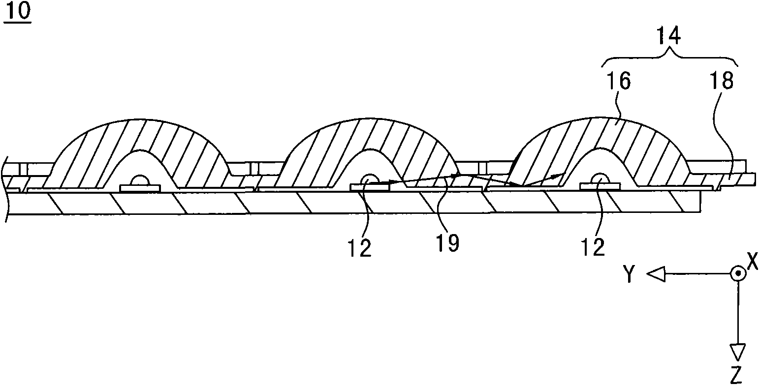
[0080] Please refer to Figure 2A and Figure 2B , which are respectively a three-dimensional structural schematic diagram and basis of an embodiment of the optical lens plate disclosed in the present invention Figure 2A Schematic diagram of the cross-sectional structure of 2B-2B. In this embodiment, the optical lens plate 200 includes a substrate 202 and thirty optical lenses 204, wherein the thirty optical lenses 204 are arranged on the substrate 202 in a 5×6 array (that is, the optical lenses arranged along the second axis Y 204 is 5, and the number of optical lenses 204 arranged in the first axis X is 6), but this embodiment is not intended to limit the present invention, that is to say, the number and arrangement of optical lenses 204 can be determined according to actual needs Adjustment. Each optical lens 204 inclu...


PUM


Abstract

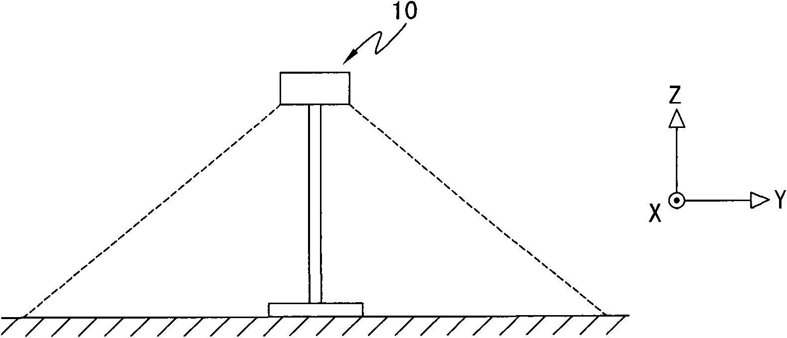
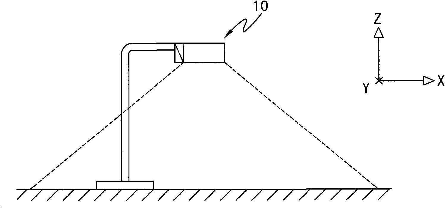
The invention relates to an optical lens and an optical lens plate. The optical lens comprises an incident light curve, a cone and an emergent light curve. Lights emitted by a light emitting diode pass through the incident curve, the cone and the emergent light curve to have a first refraction angle on a first plane, and to have a second refraction angle on a second plane. The first refraction angle is in an interval of 105-145 degrees, and the second refraction angle is in the interval of 38-65 degrees, wherein lights are asymmetrically distributed on the second plane. Therefore, utilization ratio of lights on road ends can be increased when the optical lens is applied to road lamps.

Description

technical field [0001] The invention relates to an optical lens and an optical lens plate, in particular to an optical lens and an optical lens plate which can make the light asymmetrically distributed on the second plane. Background technique [0002] With the rise of human awareness of environmental protection, various energy-saving and carbon-reducing green electronic products have received attention. Among them, light-emitting diodes (Light-Emitting Diodes, LEDs) have become the lighting fixtures attracting worldwide attention because of their small size, high brightness, long service life and low power consumption. For example, traffic lights and flashlights in daily life have been converted to light-emitting diodes as light sources. In addition to the above-mentioned traffic lights and flashlights, LEDs can also be used in street lights. [0003] In order to meet the specific light shape requirements of street lighting, the light emitted by light-emitting diodes usua...

Claims


Application Information

Patent Timeline
IPC IPC(8): F21V5/04F21Y101/02
CPCY02B20/72
Inventor 施威文
Owner LEOTEK ELECTRONICS
Learn More