Lock attaching structure and backlight module

A locking structure, backlight module technology, applied in optics, electric light sources, nonlinear optics, etc., can solve problems such as stains, debris from lock accessories and components, and scratches on diaphragm materials.

Inactive Publication Date: 2012-10-17
AU OPTRONICS CORP
View PDF3 Cites 2 Cited by
  • Summary
  • Abstract
  • Description
  • Claims
  • Application Information

AI Technical Summary

Problems solved by technology

However, in the known locking structure, the force between the locking part and the component may cause chips to fall off. Once the chips enter the backlight module, they may cause stains or scratch the film material.

Method used


Image

  • Lock attaching structure and backlight module
  • Lock attaching structure and backlight module
  • Lock attaching structure and backlight module

Examples


Embodiment Construction

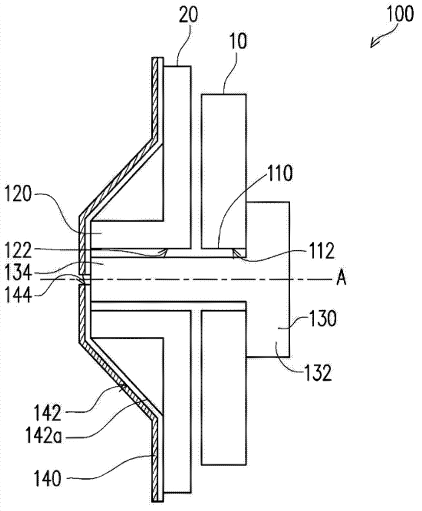
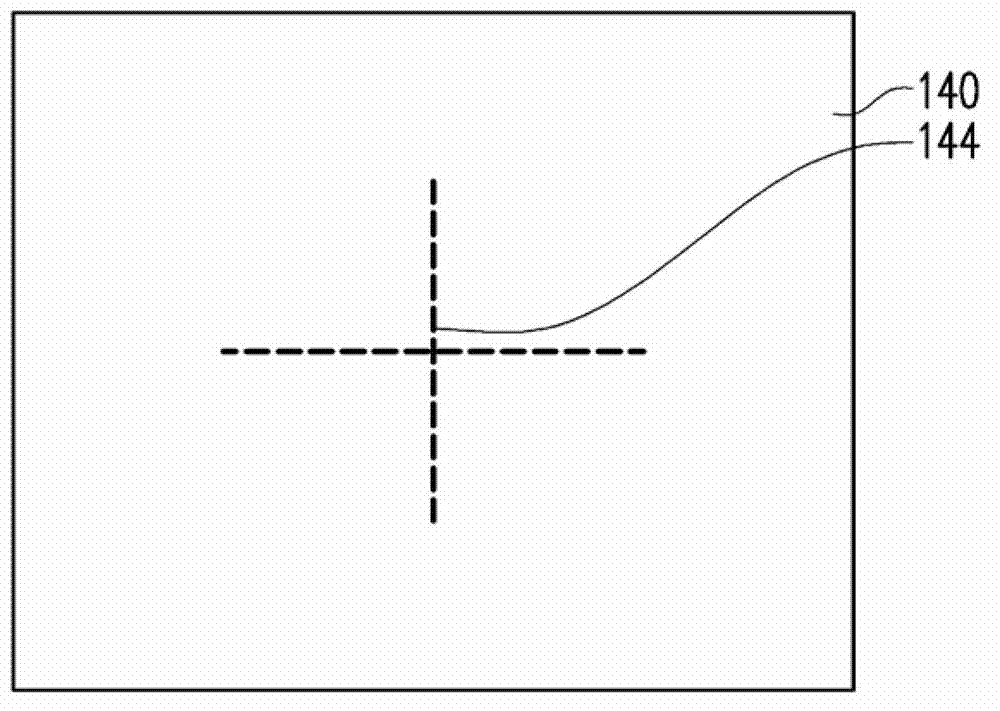
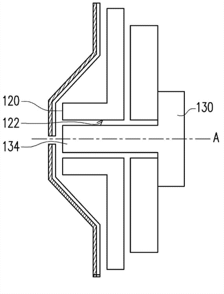
[0064] Figure 1A It is a side view of the locking structure of an embodiment of the present invention. Figure 1B for Figure 1A Front view of the diaphragm. Please refer to Figure 1A and Figure 1B , the locking structure 100 of this embodiment is used to fix the first object 10 and the second object 20 , and the locking structure 100 includes a first locking part 110 , a second locking part 120 , a locking part 130 and a diaphragm 140 . The first locking part 110 is a part of the first object 10 , and the first locking part 110 has a first assembly hole 112 . The second locking part 120 is a part of the second object 20 , and the second locking part 120 has a second assembly hole 122 . The locking part 130 includes a head 132 and an insertion part 134. The first locking part 110 is located between the second locking part 120 and the head 132. The insertion part 134 passes through the first assembly hole 112 and is locked to the second assembly hole. 122. The diaphragm ...


PUM


Abstract

The present invention discloses a lock attaching structure and a backlight module, wherein the lock attaching structure is used for fixing a first object and a second object, the lock attaching structure comprises a first lock attaching portion, a second lock attaching portion, a lock attaching member and a diaphragm, the first lock attaching portion belongs to one portion of the first object and is provided with a first assembling hole, the second lock attaching portion belongs to one portion of the second object and is provided with a second assembling hole, the lock attaching member comprises a head portion and an insertion portion, the first lock attaching portion is located between the second lock attaching portion and the head portion, the insertion portion passes through the first assembling hole and is locked to attach to the second assembling hole, the diaphragm is configured on one side of the second lock attaching portion, opposite to the first lock attaching portion and covers the second assembling hole, the diaphragm is provided with a dust collection surface opposite to the second assembling hole, and the diaphragm is provided with a through hole at a position corresponding to the second assembling hole. The present invention also discloses a backlight module containing the lock attaching structure.

Description

technical field [0001] The present invention relates to a locking structure, and in particular to a locking structure capable of effectively avoiding debris pollution and a backlight module using the locking structure. Background technique [0002] In recent years, with the vigorous development of display technology, liquid crystal displays have been widely used in daily life. For example, LCD TVs, personal computer monitors and notebook computer screens have been widely used in liquid crystal displays. The liquid crystal display is mainly composed of a backlight module and a liquid crystal display panel. The backlight module is mainly composed of a light-emitting element, a light guide plate, a diffusion sheet, a prism sheet and external mechanical components, and is used to provide the surface light source required by the liquid crystal display panel for display. The backlight module can be divided into side light emitting or direct light emitting according to the light e...

Claims


Application Information

Patent Timeline
Patent Type & Authority Applications(China)
IPC IPC(8): F21V21/00F21S8/00G02F1/13357
Inventor 王昱凯李彦霖
Owner AU OPTRONICS CORP
Why Eureka
Try Eureka