Method for measuring relationship between external load of ceramic soldering joint and metal deformation of welding line

A technology of weld metal and brazing joint, which is applied in the field of measuring the relationship between the external load of the welded joint and the deformation of the weld metal

Inactive Publication Date: 2012-10-17
HARBIN INST OF TECH
View PDF3 Cites 5 Cited by
  • Summary
  • Abstract
  • Description
  • Claims
  • Application Information

AI Technical Summary

Problems solved by technology

[0005] The purpose of the present invention is to solve the existing problem of measuring the relationship between the external load of the ceramic brazing joint and the deformation of the weld metal, and provide a method for measuring the relationship between the external load of the ceramic brazing joint and the deformation of the weld metal

Method used


Image

  • Method for measuring relationship between external load of ceramic soldering joint and metal deformation of welding line
  • Method for measuring relationship between external load of ceramic soldering joint and metal deformation of welding line
  • Method for measuring relationship between external load of ceramic soldering joint and metal deformation of welding line

Examples


specific Embodiment approach 1

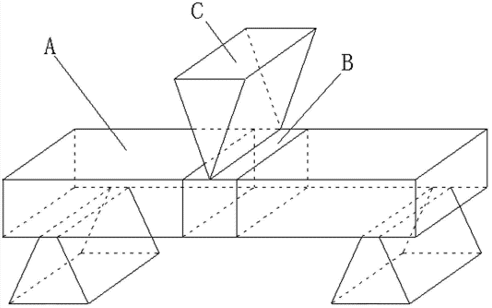
[0009] Specific implementation mode 1: This implementation mode is a method for measuring the relationship between the external load of a ceramic brazing joint and the deformation of the weld metal, which is specifically completed according to the following steps:

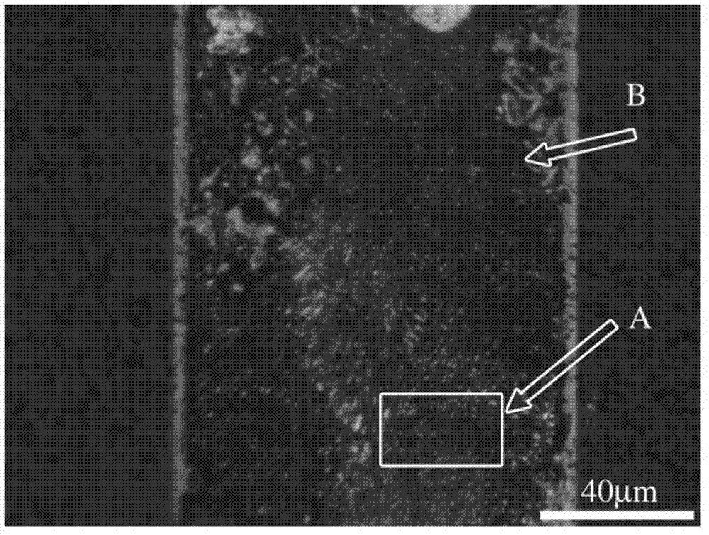
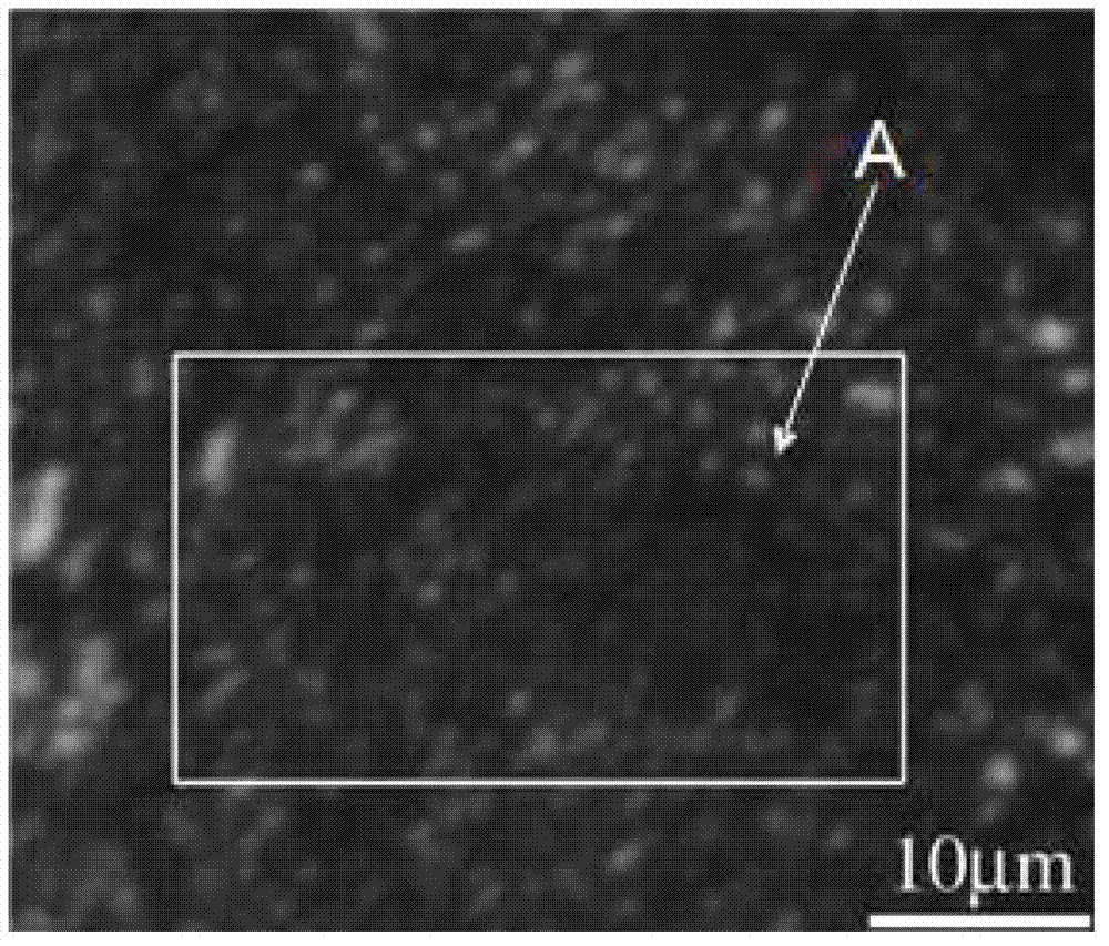
[0010] First, select the welding plate obtained by ceramic brazing as the test piece, and then conduct a three-point bending test on the test piece. The loading position of the external load is required to be directly above the center of the weld seam of the test piece, and a metallographic microscope is used in the process of carrying the external load. Record the deformation pictures of the weld under different load conditions, and then use the digital image fitting method to analyze the deformation pictures with DIC software to obtain the deformation of the weld metal under different load conditions. The relationship between the amount of deformation of the weld metal of the test piece.

[0011] This embodiment ...

specific Embodiment approach 2

[0012] Embodiment 2: The difference between this embodiment and Embodiment 1 is that a stepper motor is used to load the load, which is as follows: a stepper motor is used to drive the left-right ball screw to rotate, and the two nuts on the screw Make the two fixtures move in the same direction at the same speed at the same time, and then realize the in-situ bending of the weld seam of the piece to be tested. Others are the same as the first embodiment.

specific Embodiment approach 3

[0013] Embodiment 3: The difference between this embodiment and Embodiment 1 or 2 is that the method of segmented loading is adopted, specifically as follows: after a single loading is completed, first use a metallographic microscope to record and detect the weld seam of the welding plate. After the photo, proceed to the next load. Others are the same as those in Embodiment 1 or 2.

[0014] Adopt following test to verify effect of the present invention:


PUM


Abstract

The invention discloses a method for measuring a relationship between an external load of a ceramic soldering joint and metal deformation of a welding line, relates to a method for measuring the relationship between an external load of a welding joint and metal deformation of a welding line, and aims to solve the problem that a method for measuring the external load of the ceramic soldering joint and the metal deformation of the welding line is not available. The method comprises the following steps of: selecting a piece to be detected, performing a three-point bending test, and recording deformation pictures of the welding line under different load conditions in the process of bearing the external load by adopting a metallographic microscope; and analyzing the deformation pictures through DIC software by utilizing a digital image fitting method, namely obtaining the relationship between the external load and the metal deformation of the welding line of the piece to be detected. The invention has the advantages that the constitutive relation between the metal deformation of the welding line and the joint strength is successfully disclosed by combining the three-point bending test, the metallographic microscope and the digital image fitting method. The method is mainly used for measuring the relationship between the external load of the ceramic soldering joint and the metal deformation of the welding line.

Description

technical field [0001] The invention relates to a method for measuring the relationship between the external load of a welded joint and the deformation of the weld metal. Background technique [0002] As a new type of structural material, advanced structural ceramics are widely used in national defense, energy, aerospace, machinery, petrochemical, metallurgy, etc. , electronics and other industries are increasingly showing broad application prospects, and have attracted the attention of industrially developed countries. However, ceramic materials are brittle, low in ductility, difficult to deform and difficult to cut. In addition, the inherent brittleness of ceramic materials can lead to extremely small critical cracks, which increases the difficulty in the manufacture and processing of ceramic components and hinders their application in engineering. In order to expand the application range of ceramics, the connection problem between ceramics must be solved. A Method for ...

Claims


Application Information

Patent Timeline
Patent Type & Authority Applications(China)
IPC IPC(8): G01N3/20
Inventor 张杰贺艳明
Owner HARBIN INST OF TECH
Why Eureka
Try Eureka