
Multi-channel Parallel Laser Ultrasonic Testing System

A detection system, laser ultrasonic technology, applied in measuring devices, material analysis through optical means, instruments, etc., can solve problems such as limited detection speed, achieve high detection efficiency, fast scanning speed, and improved laser ultrasonic detection speed Effect

Inactive Publication Date: 2015-11-25
ACAD OF OPTO ELECTRONICS CHINESE ACAD OF SCI +1
View PDF6 Cites 0 Cited by
  • Summary
  • Abstract
  • Description
  • Claims
  • Application Information

AI Technical Summary

Problems solved by technology

[0004] The existing laser ultrasonic detection method is a single-channel laser ultrasonic detection technology solution, which is limited by the energy and repetition frequency of the ultrasonic excitation source and detection light source, and the detection speed is limited.

Method used


Image

  • Multi-channel Parallel Laser Ultrasonic Testing System
  • Multi-channel Parallel Laser Ultrasonic Testing System
  • Multi-channel Parallel Laser Ultrasonic Testing System

Examples


Embodiment 1

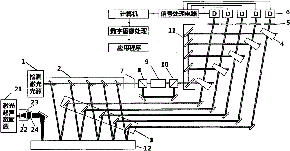
[0031] According to the instructions, a set of multi-channel parallel laser ultrasonic detection system of the present invention is produced, including a detection laser light source 1, a front beam splitting structure 2, an acquisition structure 3, a birefringent crystal 4, a polarizer 5, a detector 6, a dichotomous One wave plate 7, front polarizing beam splitting prism 8, acousto-optic modulator 9, rear polarizing beam splitting prism 10, rear beam splitting structure 11, detected object 12, laser ultrasonic excitation source 21, beam expander structure 22, bidirectional adjustable diaphragm 23, focusing mirror 24. Such as figure 1 shown. Wherein, the front splitting structure 2 can divide the signal light into 5 beams, and the collection structure 3 collects the 5 beams of signal light respectively. The front beam splitting structure 2 is a mirror group composed of 5 mirrors, the detector 6 is a scientific CCD, and the acquisition structure 3 is a mirror group composed o...

Embodiment 2

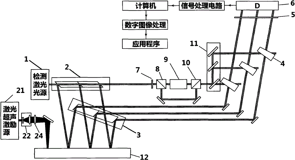
[0035] According to the instructions, a set of multi-channel parallel laser ultrasonic detection system of the present invention is produced, including a detection laser light source 1, a front beam splitting structure 2, an acquisition structure 3, a birefringent crystal 4, a polarizer 5, a detector 6, a dichotomous A wave plate 7, a front polarizing beam splitting prism 8, an acousto-optic modulator 9, a rear polarizing beam splitting prism 10, a rear beam splitting structure 11, a detected object 12, a laser ultrasonic excitation source 21, a beam expander structure 22, and a focusing mirror 24. Such as image 3shown. Wherein, the front splitting structure 2 can divide the signal light into 3 beams, and the collection structure 3 collects the 3 beams of signal light respectively. The front light splitting structure 2 is an optical structure composed of two prisms, the detector 6 is a CMOS image acquisition device, and the acquisition structure 3 is an optical structure com...


PUM


Abstract

The invention relates to a laser ultrasonic detection apparatus, belonging to the technical field of laser ultrasonic detection. The apparatus comprises a detection laser source, a front light-splitting structure, a collecting structure, a double-photorefractive lens, (a) polaroid(s), (a) detector(s), a half-wave plate, a front polarization splitting prism, an acoustic-optical modulator, a back polarization splitting prism, a back light-splitting structure, a detected piece, a laser ultrasonic excitation source, a beam-expanding structure, a bidirectional tunable aperture and a focusing mirror. The apparatus is capable of carrying out wide-range laser ultrasonic detections and the speed of the laser ultrasonic detection can be greatly raised. A linear ultrasonic excitation source is adopted to carrying out the excitation, enabling ultrasonic fields of each monitoring point to have the same distribution, and thus solving the problem that the ultrasonic intensity at each collecting point is inconsistent with each other when circular laser spots are adopted to excite the ultrasound. The apparatus has fast surface-scanning speed and high detection efficiency, and is very practical.

Description

technical field [0001] The invention relates to a novel laser ultrasonic detection device, in particular to a multi-channel parallel laser ultrasonic detection system, which belongs to the technical field of laser ultrasonic detection. Background technique [0002] Laser ultrasonic testing technology is a non-destructive testing technology that uses lasers to excite and detect ultrasound. Compared with traditional piezoelectric ultrasonic technology, laser ultrasonic testing technology has the advantages of non-contact, broadband, and point emission and reception. Therefore, it can be used in material characterization, defect detection, process monitoring, and detection or monitoring of workpieces with complex shapes or equipment in special environments such as high temperature, high pressure, corrosion, and radiation. [0003] The laser ultrasonic detection system includes a laser ultrasonic excitation system and a detection system. The laser ultrasonic excitation system d...

Claims


Application Information

Patent Timeline
Patent Type & Authority Patents(China)
IPC IPC(8): G01N21/17
Inventor 赵天卓樊仲维余锦麻云凤刘洋张雪
Owner ACAD OF OPTO ELECTRONICS CHINESE ACAD OF SCI
Learn More