Contact component

A technology for contact elements and electrical wiring, which is applied in the manufacture of contacts, electrical elements, connections, etc., can solve the problems of high cost of contact elements, and achieve the effect of improving conductive transition and reliable quality

Active Publication Date: 2012-10-17
WAGO VERW GMBH
View PDF6 Cites 5 Cited by
  • Summary
  • Abstract
  • Description
  • Claims
  • Application Information

AI Technical Summary

Problems solved by technology

The disadvantage of this design is the expensive machining of the contact elements by multiple folding

Method used


Image

  • Contact component
  • Contact component
  • Contact component

Examples


Embodiment Construction

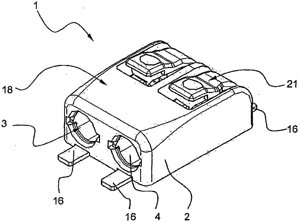
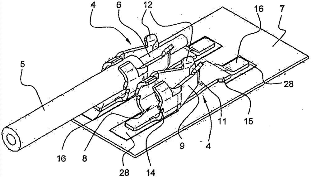
[0020] figure 1 It shows an electrical terminal 1 with an insulating material housing 2 in which metallic contact elements 4 are accommodated. The insulating material shell 2 has at least one wire lead-in hole 3 on its one end face, is used for inserting electric wire 5 ( figure 2 ). In the exemplary embodiment shown, the terminal clamp 1 is designed as a double pole, each pole having a conductor feedthrough 3 and a contact element 4 . However, the terminal clip can also have any other different number of poles.

[0021] Also from figure 1 It can be seen in the connection area 16 of the contact element 4, whose contacts make contact with the printed circuit board 7 ( figure 2 ) of the corresponding contact segment 28, such as a printed circuit. The connection area 16 is here in particular connected to the contact section 28 by a solder connection (SMD soldering), but a plug connection is also conceivable. exist figure 2 The contact element 4 fixed on the printed circ...


PUM


Abstract

The present invention relates to a contact component used for connecting an electric wire clamp of at least one electric wire, wherein the contact component (4) is prepared by a flat metal material, has a contact bottom plate (11) and at least one side wall (19) arranged from a contact bottom plate (4) along a bending line (17), the contact component (4) is a tongue sheet plate spring molded from a flat metal member, for forming a wire binding terminal on the side wall and is bended from the plane of the flat metal member to enable the free end of the plate spring (9) to form a claming rib edge towards an electric wire (5), and a seal (13) is formed between the contact bottom plate (11) and the plate spring (9). According to the present invention, in the area of the seal root (13a) at the tail end of the seam (13) there is provided an embossed pattern (22) for reducing the width of the seam (13).

Description

technical field [0001] The invention relates to a contact element of an electrical terminal block for connecting at least one electrical conductor, wherein the contact element is formed from a flat metal material and has a contact base and at least one side wall arranged along a bending line from the contact base, and the contact element To form a conductor terminal, the side wall has a tongue-shaped leaf spring formed from a flat metal part, which is bent out of the plane of the flat metal part in such a way that the free end of the leaf spring forms a clamping position towards the electrical conductor. edge and form a gap between the contact base plate and the leaf spring. Background technique [0002] In the case of contact elements according to the general concept with punched-out leaf springs, a slot with a certain minimum width is produced between the contact base plate and the leaf spring due to processing technology. The slot width can vary depending on the bending ...

Claims


Application Information

Patent Timeline
Patent Type & Authority Applications(China)
IPC IPC(8): H01R11/11H01R4/48H01R43/16
CPCH01R4/4836H01R4/48365
Inventor S·加索尔
Owner WAGO VERW GMBH
Why Eureka
Try Eureka