
Automatic assembling terminal machine

A technology of automatic assembly and terminal machine, which is applied in the assembly/disassembly of contacts, etc., which can solve the problems of low production efficiency, inability to handle complex terminals, and low product accuracy

Active Publication Date: 2012-10-17
广西昭信平洲电子有限公司
View PDF5 Cites 14 Cited by
  • Summary
  • Abstract
  • Description
  • Claims
  • Application Information

AI Technical Summary

Problems solved by technology

The assembly device cannot handle complex terminals, the simple structure of the equipment leads to low production efficiency, and the precision of the product is relatively low

Method used


Image

  • Automatic assembling terminal machine
  • Automatic assembling terminal machine
  • Automatic assembling terminal machine

Examples


Embodiment 1

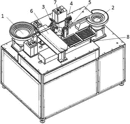
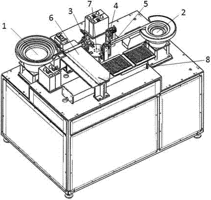
[0023] In general, figure 1 Shows the structure of the automatic terminal assembly machine according to the first embodiment of the present invention, as figure 1 As shown, the automatic terminal assembly machine of the present invention includes a pick-and-place unit, a magnetic nest alignment unit 1 , a terminal alignment unit 2 , a magnetic nest placement unit 3 , a terminal placement unit 4 , and a terminal assembly unit 5 .

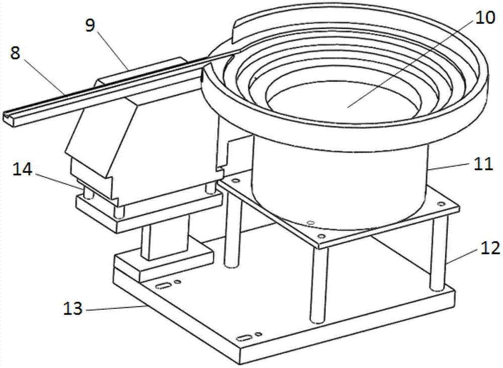
[0024] Specifically, figure 2 It shows the structure of the magnetic socket alignment unit of the automatic assembly terminal machine according to the present invention, such as figure 2 As shown, the magnetic nest alignment unit structure of the present invention includes a magnetic nest direct vibration guide rail 8, a magnetic nest direct vibration 9, a magnetic nest vibration plate 10, a magnetic nest circular vibration 11, a circular vibration support 12, a fixed plate 13, and a direct vibration support. 14.

[0025] The magnetic nest circu...

Embodiment 2

[0041] The structure of the automatic assembly terminal machine of the second embodiment of the present invention is as follows Figure 8 shown. The automatic assembly terminal machine of the second embodiment has basically the same components and functions as the automatic assembly terminal machine of the first embodiment, and the same units also use the same reference numerals. The only difference is that after the assembly is completed, The products are neatly arranged on the assembly rod fixture through the cooperation of the picking unit and the delivery unit, so as to speed up the output of the products. The automatic terminal assembly machine in the second embodiment of the present invention may also preferably include a picking unit 7 and a delivery unit 8 . Those skilled in the art should understand that the above two units can also be used in the automatic terminal assembly machine of the first embodiment.

[0042] Specifically, Figure 9 Shows the picking unit st...


PUM


Abstract

The invention discloses an automatic assembling terminal machine. The automatic assembling terminal machine comprises a pick-and-place unit, and is characterized by also comprising a magnetic nest alignment unit, a terminal alignment unit, a magnetic nest placing unit, a terminal placing unit and a terminal assembling unit. Compared with the prior art, a spring cord chew is used for fixing a rectangular magnetic nest, and terminals are sucked up by using a vacuum principle, are placed in opposite positions on two sides of the magnetic nest, are accurately hung on the two sides of the magnetic nest by using the movement principle of the air, and then are accurately put into the magnetic nest through the cooperation of a spring and a roller. On the other hand, after finishing assembly, by the automatic assembling terminal machine, products are orderly arranged on an assembling rod fixture through the cooperation of a goods taking unit and a goods delivering unit. Through the automatic assembling terminal machine, a production line can be optimized, the working efficiency is improved, and the labor consumption is reduced, thus the production cost is lowered.

Description

technical field [0001] The present invention relates to terminal assembly technology, and more specifically, the present invention relates to an automatic terminal assembly machine. Background technique [0002] In the electrical and electronic industry, transformers, wire-wound resistors, inductors and other products usually require terminal assembly during the manufacturing process. In the past, this process can only be manually operated by workers, which not only wastes a lot of human resources, but also has low efficiency. With the development of technology, the current terminal assembly work is gradually assisted by machines. [0003] In the prior art, the terminals need to be injection-molded to make the terminals flush. During processing, the terminal strips are placed corresponding to the mold. Usually, the depth and position of the terminals are easily different, which brings inconvenience to the processing and molding, and it is difficult to increase the processin...

Claims


Application Information

Patent Timeline
IPC IPC(8): H01R43/20
Inventor 汪林李培涛黄国文王业辉卢超雄潘冬文
Owner 广西昭信平洲电子有限公司
Learn More