Plugging device for circuit board and server

A technology for plugging and unplugging devices and circuit boards, which is applied in the directions of servers, circuits, coupling devices, etc., can solve problems such as difficulty in realizing hot plugging and unplugging of PCI-E cards.

Active Publication Date: 2012-10-17
HUAWEI TECH CO LTD
View PDF5 Cites 23 Cited by
  • Summary
  • Abstract
  • Description
  • Claims
  • Application Information

AI Technical Summary

Problems solved by technology

[0004] Since the connector of the PCI-E card is perpendicular to the interface of the installation panel, the chassis cover must be o

Method used


Image

  • Plugging device for circuit board and server
  • Plugging device for circuit board and server
  • Plugging device for circuit board and server

Examples


Embodiment 1

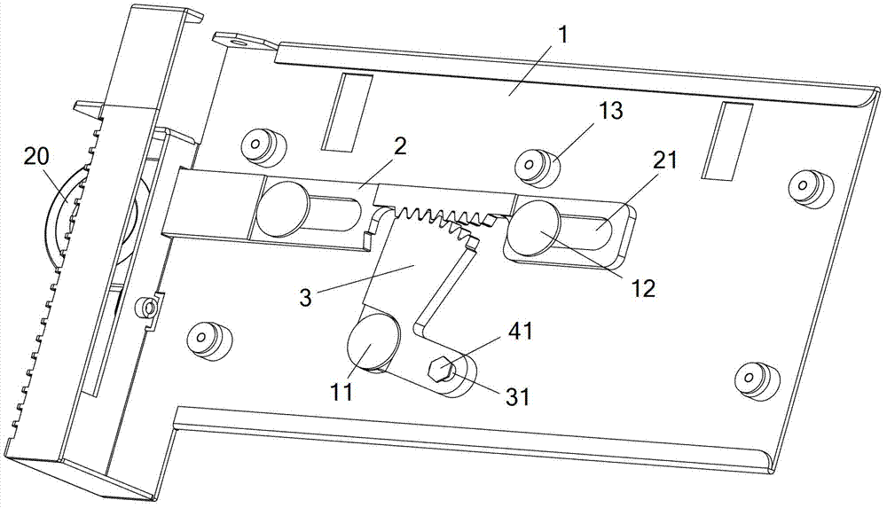
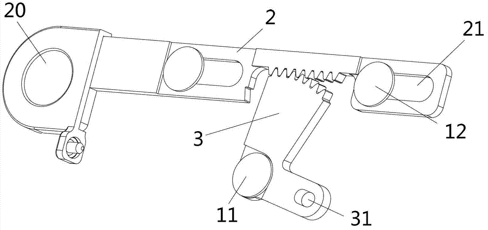
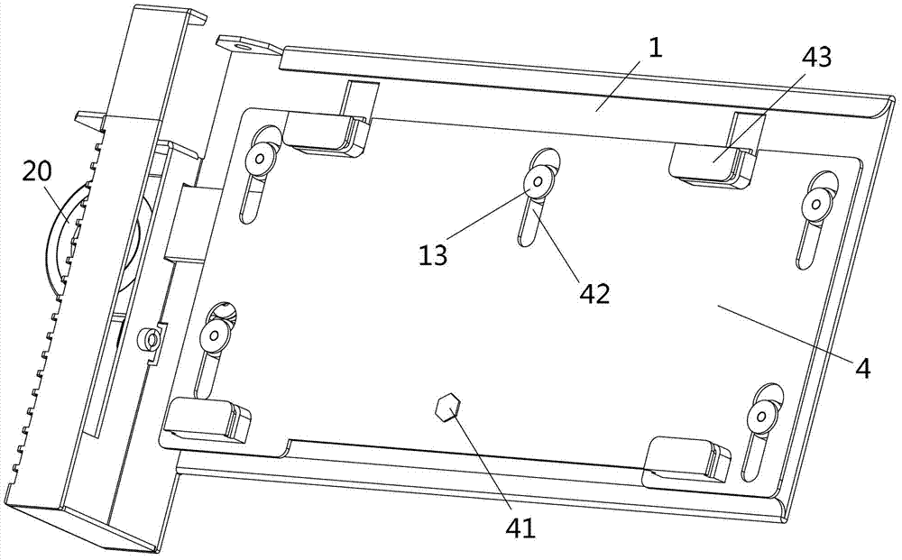
[0031] Such as figure 1 , figure 2 and image 3 As shown, the circuit board insertion and extraction device provided by the embodiment of the present invention includes a base plate 1, a pull bar 2, a rotating member 3 and a carrier plate 4, wherein the pulling bar 2 and the rotating member 3 are located between the carrier plate 4 and the base plate 3 .

[0032] The pull bar 2 is movably connected with the bottom plate 1 through a transverse guiding mechanism, and the bar body of the pull bar 2 is provided with sawtooth. One end of the pull bar 2 extends out of the board surface of the bottom plate 1 and forms a handle 20 as a handle when moving the pull bar 2 . The rotating part 3 is in the shape of a broken line, and the bending angle is preferably 90°. The rotating part 3 includes a first arm, a first rotating shaft (or hinge) 11 and a second arm. The first rotating shaft 11 is arranged at the turning point of the rotating part 3. A rotating shaft 11 is used for movab...

Embodiment 2

[0044] This embodiment is basically the same as Embodiment 1, the difference is: as Figure 7 and Figure 8 As shown, in this embodiment, the transmission mechanism includes a transmission guide groove 412 arranged on the carrier plate 4, and a first fixed pin 312 sleeved in the transmission guide groove 412, and the first fixed pin 312 is fixed on the rotating member (Fig. not shown in the second arm). Preferably, the transmission guide groove 412 extends laterally, and the length of the transmission guide groove 412 is defined as the lateral movement range of the first fixing pin 312 during the rotation of the rotating member.

[0045] When the rotating member 3 rotates, under the cooperation of the first fixed pin 312 and the longitudinal guide mechanism, the carrier plate 4 is driven to move longitudinally, and at the same time, the first fixed pin 312 also slides laterally in the transmission guide groove 412 relative to the carrier plate 4 .

[0046] It should be noted...

Embodiment 3

[0048] This embodiment is basically the same as Embodiment 2, the difference is: as Figure 9 As shown, in this embodiment, there are two rotating parts 3 , and the saw teeth at the end of the first arm of each rotating part 3 are engaged with the saw teeth on the pull bar 2 .

[0049] The pull bar 2 drives the two rotating parts 3 to rotate synchronously, and the two rotating parts 3 synchronously drive the carrier plate (not shown in the figure) to move longitudinally, that is, there are two stress points on the carrier plate, so that the carrier plate The force is more balanced and the moving process is more stable. In addition, if one of the rotating parts is damaged, the other rotating part can also independently drive the carrier plate to move longitudinally.


PUM


Abstract

The embodiment of the invention discloses a plugging device for a circuit board and a server, and belongs to the technical field of electronic assembly. The technical problem that a peripheral component interconnect express (PCI-E) card is difficultly subjected to hot plugging in the prior art is solved. The plugging device for the circuit board comprises a base plate, a pulling strip, rotating members and a carrier plate, wherein the pulling strip is movably connected with the base plate through a transverse guiding mechanism; sawteeth are formed on the body of the pulling strip; the pulling strip comprises a handle which is extended out of the base plate; the rotating members are in fold line shapes; each rotating member comprises a first arm, a first rotation shaft and a second arm; the first rotation shaft is arranged at the turning of each rotating member and is used for movably connecting each rotation member and the base plate; sawteeth are formed at the tail end of the first arm and are engaged with the sawteeth on the pulling strip; the second arm is movably connected with the carrier plate through a transmission mechanism; the carrier plate is movably connected with the base plate through a longitudinal guiding mechanism; and clamping slots are formed on the carrier plate and are used for fixing the circuit board. The plugging device is applied to the plugging of the circuit board in electronic equipment.

Description

technical field [0001] The invention belongs to the technical field of electronic assembly, and in particular relates to a circuit board insertion and extraction device and a server. Background technique [0002] PCI-E card (Peripheral Component Interconnect Express card) is used for the interconnection of peripheral components of computers or communication platforms, and is widely used in products such as servers. In order to increase the maintainability of the equipment and assembly needs, the PCI-E card can also support hot swapping. [0003] The connector (also known as golden finger) of the PCI-E card and the installation panel are respectively located on the two adjacent sides of the PCI-E card, so the interface directions of the connector and the installation panel are perpendicular to each other. At present, to insert the connector of the PCI-E card into the slot of the chassis, it is necessary to open the chassis cover first, put the PCI-E card into the chassis, an...

Claims


Application Information

Patent Timeline
IPC IPC(8): H01R43/26G06F1/18
CPCG06F1/185H05K7/1489H01R13/62944G06F1/18H01R12/7058H01R43/26H01R12/725H01R12/7005H05K7/1485
Inventor 李爽李尧敖峰
Owner HUAWEI TECH CO LTD
Why Eureka
Try Eureka