Power supply system of remote sensing platform of unmanned plane

A technology of power supply system and machine remote sensing, which is applied in electrical components, circuit devices, emergency power supply arrangements, etc., can solve problems such as unfavorable battery unified management, increased operational risk, and power supply system confusion, to improve power supply stability, improve safety and reliability. the effect of reducing electromagnetic interference

Active Publication Date: 2012-10-17
ZHEJIANG UNIV
View PDF2 Cites 32 Cited by
  • Summary
  • Abstract
  • Description
  • Claims
  • Application Information

AI Technical Summary

Problems solved by technology

At present, there are two main power supply methods for UAV remote sensing platforms: one is to use multiple lithium batteries with different output voltages for decentralized power supply. This method is not conducive to the unified management of batteries. It becomes confusing, and multiple batteries take up more space and loads, which increases the burden on the UAV remote sensing platform; another way is to use a single battery to convert multiple DC-DC (DC-DC) into different types of voltages to supply power separately, And each load uses multiple sets of DC-DC parallel work to form a redundant power supply method to improve system security. Although this method can greatly improve the stability of power supply, the parallel operation of multiple DC-DC conversion circuits increases electromagnetic interference. , and the ground operators cannot know the failure of the circuit in time, which increases the operational risk
[0004] At present, operators of UAV remote sensing platforms judge the working time of batteries based on experience. This method of relying on experience increases the requirements for operators, and the experience is not very accurate, which reduces the efficiency of battery use.

Method used


Image

  • Power supply system of remote sensing platform of unmanned plane
  • Power supply system of remote sensing platform of unmanned plane
  • Power supply system of remote sensing platform of unmanned plane

Examples


Embodiment Construction

[0025] In order to describe the present invention more specifically, the technical solutions and working principles of the present invention will be described in detail below in conjunction with the accompanying drawings and specific embodiments.

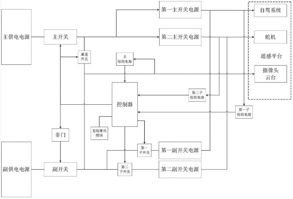
[0026] Such as figure 1 As shown, a power supply system for an unmanned aerial vehicle remote sensing platform includes: a main power supply, a secondary power supply, a main switch, a secondary switch, a channel switch, a controller, a wireless communication module, and a NOT gate , a main detection circuit, two sub-switches, two sub-detection circuits, two main switching power supplies and two auxiliary switching power supplies; wherein: the output end of the main power supply is connected to one end of the main switch, and the output end of the auxiliary power supply is connected to the auxiliary One end of the switch is connected, the control pole of the main switch is connected with the input terminal of the NOT gate, the contr...


PUM


Abstract

The invention discloses a power supply system of a remote sensing platform of an unmanned plane. The power supply system comprises a main power source, an assistant power source, a main switch, an assistant switch, a channel switch, a controller, a NOT gate, a main detection circuit, n main switch power sources and n assistant switch power sources. A main battery and an assistant battery with different capacities are used for power supply, and when the main battery is low, the assistant battery can be switched for backup, so that the manageability of the batteries are improved, and volume load of the unmanned plane can not be increased too much; and according to the power supply system of the remote sensing platform of the unmanned plane, the output voltage amplitude of the power source and the input voltage amplitude of each load can be detected in real time by the detection circuit, and when the output voltage of the main power source is lower the preset voltage amplitude, the assistant power source is switched to supply power in time, an alarm is sent to a monitoring person on the ground to enable the monitoring person to take action to force the unmanned plane to land, and the safety and the reliability of the unmanned plane are improved.

Description

technical field [0001] The invention belongs to the technical field of aerospace power supply, and in particular relates to a power supply system for an unmanned aerial vehicle remote sensing platform. Background technique [0002] As a highly automated and intelligent equipment and technical means, drones have the function of extending human hands, feet, eyes and ears, and brain, and expanding human capabilities. UAVs can be widely used in economic construction, ecological protection, social development, national defense and scientific research. In economic construction, it can be widely used in aerial remote sensing and industrial and agricultural aviation operations. Such as aerial photography, aerial prospecting, aerial surveying and mapping, disaster monitoring, traffic monitoring, agricultural and forestry aerial seeding, meteorological observation and artificial precipitation, etc. In ecological protection, it can be used in air and water pollution monitoring, compr...

Claims


Application Information

Patent Timeline
Patent Type & Authority Applications(China)
IPC IPC(8): H02J9/06
Inventor 何勇
Owner ZHEJIANG UNIV
Why Eureka
Try Eureka