Motor
A motor and magnet technology, applied in the field of inner rotor type motors, can solve problems such as difficulties, achieve the effect of stabilizing the back electromotive force waveform and suppressing the axial size
- Summary
- Abstract
- Description
- Claims
- Application Information
AI Technical Summary
Problems solved by technology
Method used
Image
Examples
no. 1 Embodiment approach
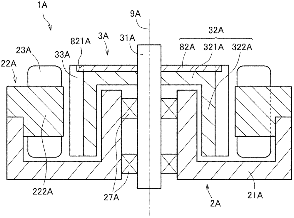
[0054] figure 1 It is a longitudinal sectional view of a motor 1A according to the first embodiment of the present invention. like figure 1 As shown, the motor 1A has a stationary part 2A and a rotating part 3A. The rotating part 3A rotates around the central axis 9A extending up and down.
[0055] The rotating unit 3A has a shaft 31A, a magnet holder 32A, and a plurality of magnets 33A. The shaft 31A is arranged along the central axis 9A. The magnet holder 32A has a cover portion 321A and a cylindrical portion 322A. The cover portion 321A is fixed to the shaft 31A. The cylindrical portion 322A extends downward from the outer peripheral portion of the cover portion 321A. The magnet 33A is fixed to the outer peripheral surface of the magnet holder 32A.
[0056] The stationary part 2A has a case 21A, a stator core 22A, a coil 23A, and a bearing part 27A. The coil 23A is disposed radially outside the magnet 33A. The stator core 22A has a plurality of teeth 222A serving a...
no. 2 Embodiment approach
[0060]
[0061] Next, a second embodiment of the present invention will be described.
[0062] The motor of the present embodiment is installed in home appliances such as air conditioners and refrigerators, and is used as a drive source for fans and pumps. However, the motor of the invention may also be a motor for other known applications. For example, the motor of the present invention may be installed in OA (Office Automation) equipment, medical equipment, automobiles, etc., and generate various driving forces. Hereinafter, the device on which the motor 1 is mounted is referred to as a "drive device".
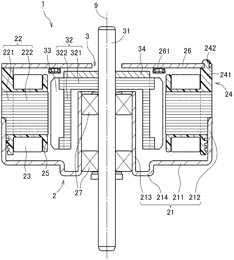
[0063] figure 2 It is a vertical cross-sectional view of the motor 1 according to this embodiment. like figure 2 As shown, the motor 1 has a stationary part 2 and a rotating part 3 . The stationary part 2 is fixed to the frame of the driving device. The rotating part 3 is rotatably supported with respect to the stationary part 2 .
[0064] The stationary part 2 of t...
no. 3 Embodiment approach
[0110] Next, the third embodiment of the present invention will be described focusing on the differences from the second embodiment. Figure 7 It is a vertical cross-sectional view of a motor 1B according to the third embodiment. Figure 7 The motor 1B differs from the motor 1 of the second embodiment in terms of the configuration of the magnet holder 32B and the presence of the encoder 28B.
[0111] First, the configuration of the magnet holder 32B will be described. Figure 7 The magnet holder 32B has a rotor core 81B and a positioning plate 82B. The rotor core 81B has a cover portion 321B and a cylindrical portion 322B. The cover portion 321B is a substantially disk-shaped portion that expands radially above the bearing portion 27B. The inner peripheral portion of the cover portion 321B is fixed to the outer peripheral surface of the shaft 31B. The cylindrical portion 322B is a substantially cylindrical portion extending downward from the outer peripheral portion of the...
PUM
 Abstract
Description
Claims
Application Information
 - R&D
- Intellectual Property
- Life Sciences
- Materials
- Tech Scout
- Unparalleled Data Quality
- Higher Quality Content
- 60% Fewer Hallucinations
Browse by: Latest US Patents, China's latest patents, Technical Efficacy Thesaurus, Application Domain, Technology Topic, Popular Technical Reports.
© 2025 PatSnap. All rights reserved.Legal|Privacy policy|Modern Slavery Act Transparency Statement|Sitemap|About US| Contact US: help@patsnap.com


