
Vehicle drive device

A driving device and vehicle technology, which is applied in the direction of transmission device, electrical device, power device, etc., can solve the problems of difficulty in realizing the driving device, increase in radial size, and difficulty in ensuring the diameter of the hydraulic coupling fully, and achieve the purpose of suppressing the shaft To the effect of size expansion

Inactive Publication Date: 2014-09-03
AISIN AW CO LTD +1
View PDF4 Cites 5 Cited by
  • Summary
  • Abstract
  • Description
  • Claims
  • Application Information

AI Technical Summary

Problems solved by technology

Therefore, there is a problem that the radial dimension of the periphery of the coupler-side connecting portion has to be increased, making it difficult to reduce the radial dimension of the drive device.
In addition, since the diameter of the fluid coupling [torque converter 1] needs to be smaller than the diameter of the coupler-side coupling portion, there is a problem that it is difficult to secure sufficient mounting space on the vehicle side where the drive unit is mounted. The diameter of the fluid coupling [torque converter 1], which leads to a decrease in the performance and efficiency of the fluid coupling [torque converter 1]

Method used


Image

  • Vehicle drive device
  • Vehicle drive device
  • Vehicle drive device

Examples


Embodiment Construction

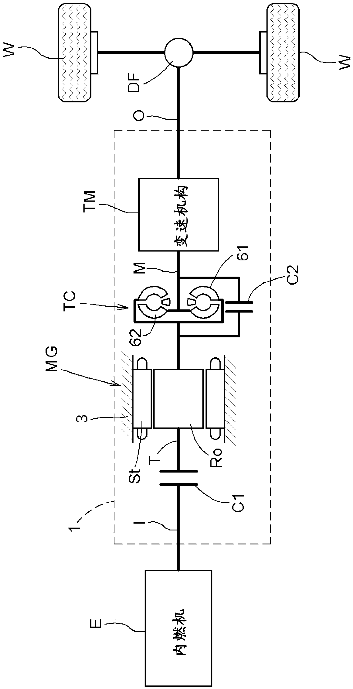
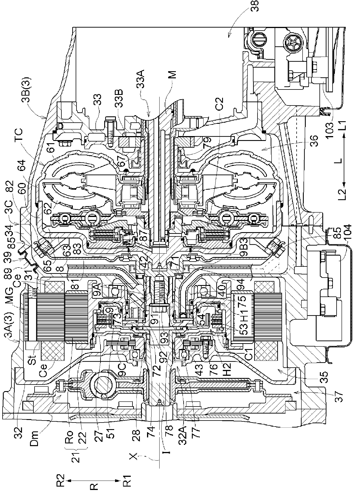
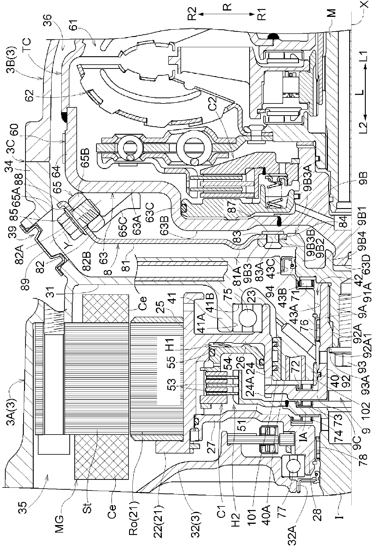
[0033] Embodiments of the vehicle drive device according to the present invention will be described with reference to the drawings. In addition, in the following description, unless otherwise specified, the rotation axis of the rotary electric machine MG ( figure 2 "Axial direction L", "radial direction R", and "circumferential direction" are defined based on the axis X) shown. Also, "axis first direction L1" means a direction along the axial direction L from the side of the rotary electric machine MG toward the side of the torque converter TC ( figure 2 The right side in ), "Axis second direction L2" indicates the direction opposite to the first axis direction L1 ( figure 2 left in ). In addition, the "radial inner direction R1" indicates the direction toward the inner side in the radial direction R, and the "radial outer direction R2" indicates the direction toward the outer side in the radial direction R. In addition, the direction of each component indicates the dire...


PUM


Abstract

A vehicle drive device is realized having a configuration in which a rotor member of an electric rotary machine and a rotating housing of a fluid coupling are linked via a disk-shape member, wherein the drive device is kept compact in the radial dimension, ensuring easy mountability on a vehicle. A rotor member (21) and a rotating housing (60) are linked via a disk-shape member (8), and an outer peripheral fixing part (81) of the disk-shape member (8) is formed in the shape of a truncated cone surface which, from the side of the electric rotary machine (MG) to the side of the fluid coupling (TC) in the axial direction (L), expands outwards in the radial direction (R). The coupling-side linking part of the fluid coupling (TC) is fixed to the rotation housing (60) in a position having a portion overlapping with the rotor housing (60) seen from the axial direction (L), and has a linking contact surface (65A) contacted by the outer peripheral fixing part (82). The linking contact surface (65A) is provided so as not to overlap with the electric rotary machine (MG) seen in the direction orthogonal to said linking contact surface (65A).

Description

technical field [0001] The present invention relates to a vehicle drive device including a rotating electric machine and a fluid coupling arranged coaxially with the rotating electric machine on one side in the axial direction of the rotating electric machine. Background technique [0002] As for the drive device for a vehicle as described above, for example, there is a technique described in Japanese Patent Application Laid-Open No. 2006-137406 (Patent Document 1). In addition, in the description of this background art column, the component names of patent document 1 are quoted within parentheses and demonstrated. In the structure described in Patent Document 1, as in the document figure 1 As shown, the rotor member [rotor 12 and drum member 13] of the rotating electrical machine [electric motor] and the rotating housing of the fluid coupling [torque converter 1] pass through the disc-shaped member [plate member 10] and the connecting member [Second spline shaft 11] and c...

Claims


Application Information

Patent Timeline
Patent Type & Authority Applications(China)
IPC IPC(8): F16H41/24B60K6/26B60K6/36B60K6/405B60K6/48B60L11/14H02K7/10B60L50/16
CPCB60K6/405F16H41/24H02K7/003F16H2057/02034F16H57/025Y02T10/6221H02K7/006B60K6/387B60K6/48B60L3/0061B60L15/2054B60L2220/50B60L2240/36B60L2240/486B60L2240/507B60L50/16Y02T10/62Y02T10/64Y02T10/7072Y02T10/72Y02T10/70
Inventor 岩濑干雄须山大树神内直也冲岛达矢井上雄二出盐幸彦
Owner AISIN AW CO LTD
Learn More