
In-wheel motor unit for a vehicle

a technology for in-wheel motors and vehicles, applied in the direction of electric propulsion mounting, couplings, transportation and packaging, etc., can solve the problems of deteriorating vehicle mountability and consequently lowering displacement absorption performance, and achieve excellent automotive layout properties and higher displacement absorption performan

Inactive Publication Date: 2016-03-10
NISSAN MOTOR CO LTD
View PDF0 Cites 6 Cited by
  • Summary
  • Abstract
  • Description
  • Claims
  • Application Information

AI Technical Summary

Benefits of technology

The present invention provides an in-wheel motor unit for a vehicle that solves the problem of deteriorated vehicle mountability and lowered displacement absorbing performance in conventional techniques. The unit achieves both the ensuring of vehicle mountability and the displacement absorbing performance by configuring the second outer tooth portion of the gear coupling shaft of the displacement absorption mechanism to be placed axially in the vehicle outer or exterior side with respect to a wheel mounting surface of the wheel hub shaft. This results in a more compact and efficient in-wheel motor unit that allows for better automotive layout properties and higher displacement absorption performance.

Problems solved by technology

Therefore, with respect to the position of the wheel, the drive unit body is shifted toward the interior side by the entire length in the axial direction of the displacement absorbing mechanism, which could deteriorate vehicle mountability.
Further, when the drive unit body is placed forcibly in the vehicle outer side, the axial span of the displacement absorption mechanism is shortened so that there is a possibility that the displacement absorbing performance is consequently lowered.

Method used


Image

  • In-wheel motor unit for a vehicle
  • In-wheel motor unit for a vehicle
  • In-wheel motor unit for a vehicle

Examples


Embodiment Construction

[0022]Hereinafter, a description is given of the best configuration for implementing an in-wheel motor unit for a vehicle according to the present invention based on a first embodiment shown in the drawings.

[0023]First, a description is made of the configuration. More specifically, the configuration of the vehicle in-wheel motor unit in the first embodiment is described separately in the following sections: schematic configuration of the entire unit; detailed configuration of the drive unit body; detailed configuration of displacement absorption mechanism; detailed configuration of wheel structure; detailed configuration of assembly structure of gear coupling axis; and detailed configuration of the periphery of axle case, respectively.

Schematic Configuration of the Entire Unit

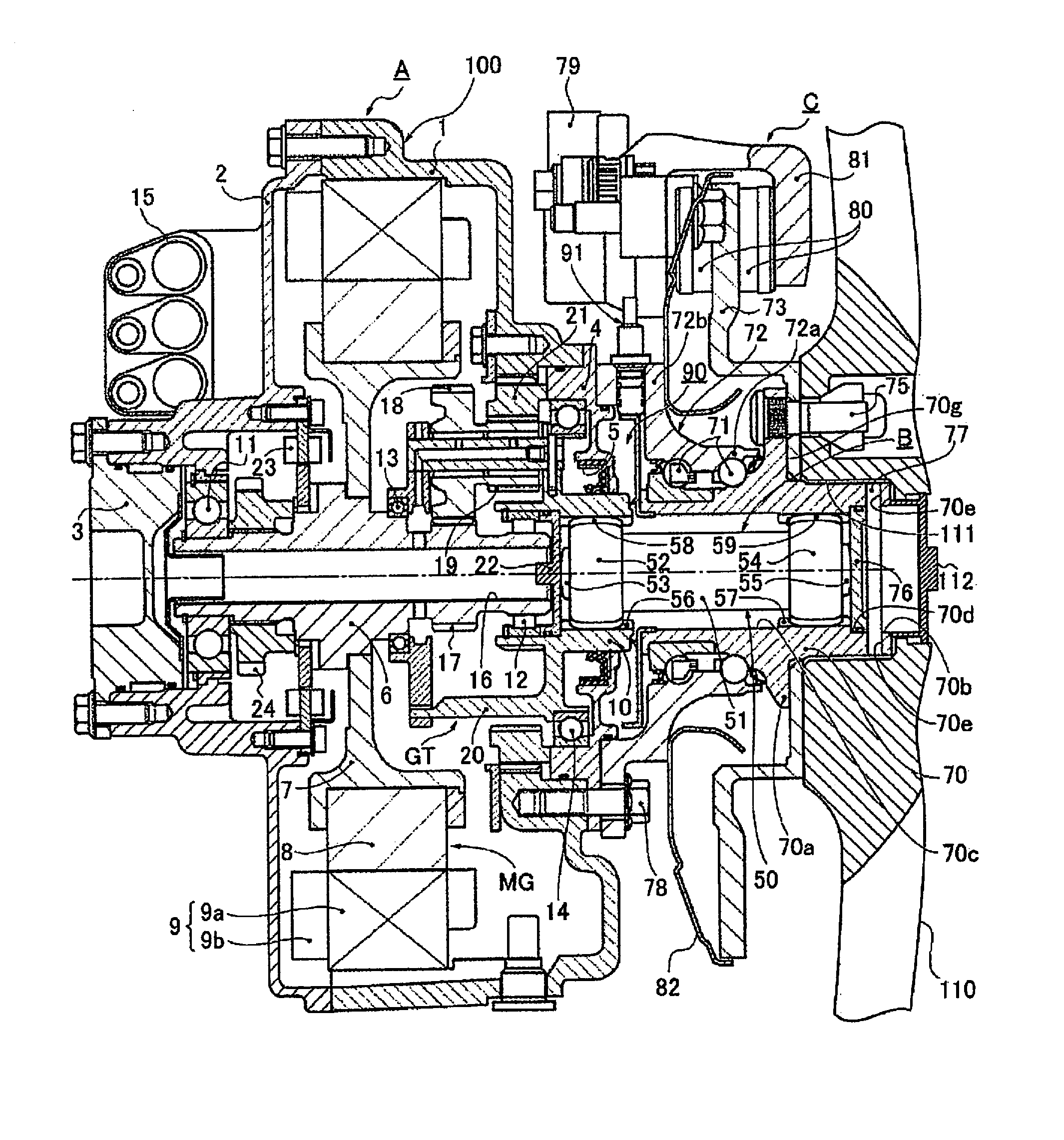
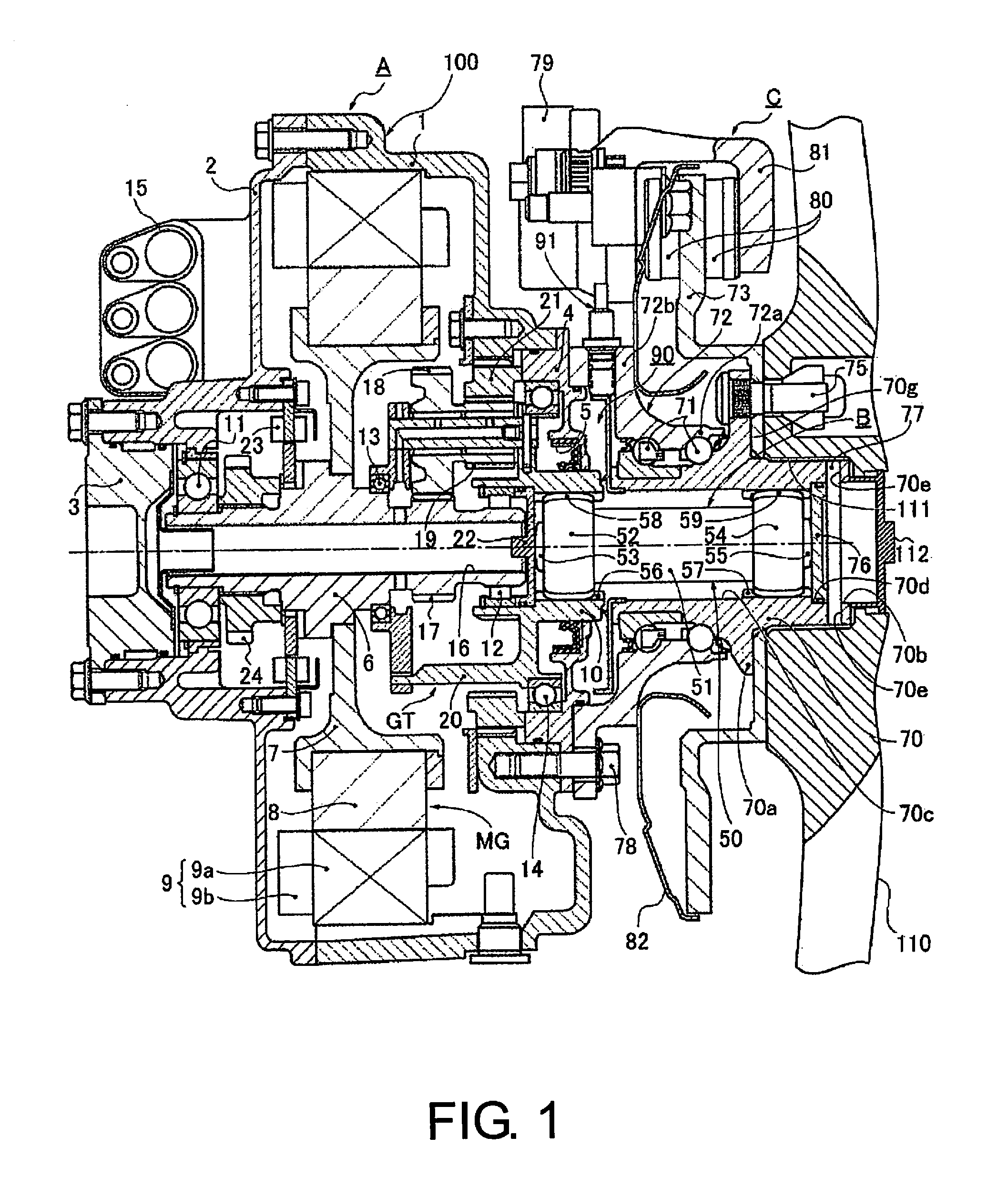
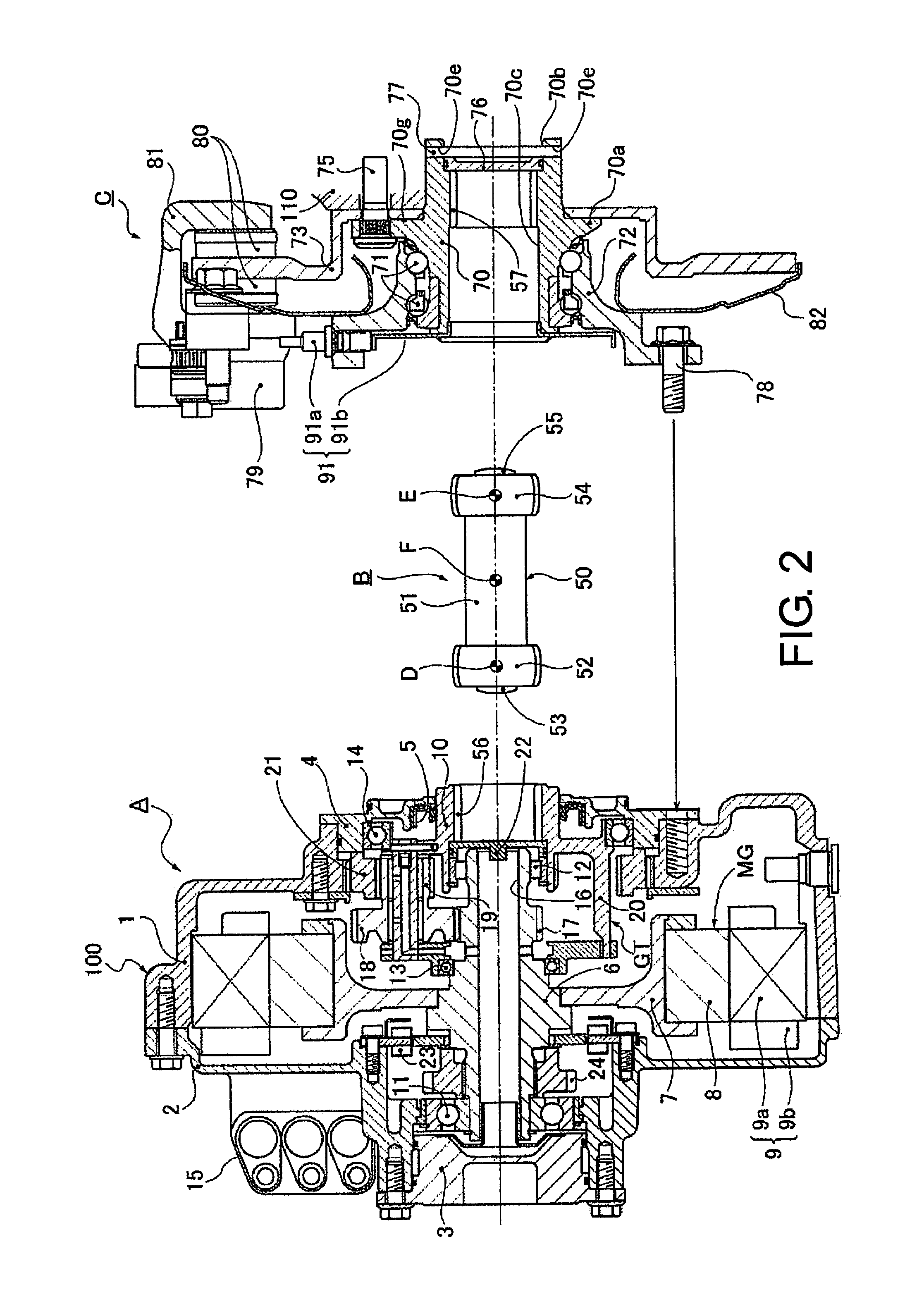
[0024]With reference to FIG. 1 showing an overall cross-section of the in-wheel motor unit for a vehicle, a description will be given of a schematic structure of the entire unit. The in-wheel motor unit for the...


PUM


Abstract

An in-wheel motor unit for a vehicle having a drive output shaft of a drive unit body and a wheel hub shaft supported by a hub bearing with respect to a case member of the drive unit body are connected via a displacement absorption mechanism. The displacement absorption mechanism comprises an output shaft side drive transmission fitting portion allowing a first inner tooth portion of the drive output shaft to mesh with a first outer tooth portion of a gear coupling shaft, and a hub shaft side drive transmission fitting portion allowing a second inner tooth portion of the wheel hub shaft to mesh with a second outer tooth portion of the gear coupling shaft, the second outer tooth portion being arranged axially in the vehicle exterior side with respect to a wheel mounting surface on which a tire wheel is mounted to the wheel hub.

Description

CROSS-REFERENCE TO RELATED APPLICATIONS[0001]This application is a U.S. National stage application of International Application No. PCT / JP2014 / 059250, filed Mar. 28, 2014, which claims priority based on Japanese Patent Application No. 2013-082666, filed in Japan Patent Office on Apr. 11, 2013, the contents of each of which is hereby incorporated herein by reference.BACKGROUND[0002]1. Field of the Invention[0003]The present invention relates to an in-wheel motor unit for a vehicle in which a drive output shaft of the drive unit body and a wheel hub shaft supported by the hub bearing with respect to a case member are linked or connected via a displacement absorption mechanism.[0004]2. Background Information[0005]Conventionally, an in-wheel motor for a vehicle is known in which a drive output shaft and a wheel hub shaft supported by a hub bearing is connected via a displacement absorption mechanism. The displacement absorption mechanism is intended to prevent or suppress the displaceme...

Claims


Application Information

Patent Timeline
Patent Type & Authority Applications(United States)
IPC IPC(8): B60K7/00B60K17/14
CPCB60K17/14B60K7/0007B60B27/0015B60K17/046B60K2007/0038B60K2007/0092F16D3/185
Inventor ABE, MANABUCHIBA, RYOSENOO, TAKASHIASOGAWA, KATSUNORI
Owner NISSAN MOTOR CO LTD
Learn More