
Drive apparatus for electric vehicle

Inactive Publication Date: 2009-11-05
TOYOTA JIDOSHA KK
View PDF11 Cites 3 Cited by
  • Summary
  • Abstract
  • Description
  • Claims
  • Application Information

AI Technical Summary

Benefits of technology

[0009]Problems to be solved by the present invention are that, in a drive apparatus for an electric vehicle, the outline of the drive apparatus is increased in size and vehicle mountability is worsened because a power cable is led out, and that a problem with routing of the power cable is caused.
[0010]The present invention has been made in light of the above problems. An object of the present invention is to provide a drive apparatus for an electric vehicle having improved mountability.
[0013]According to the drive apparatus for an electric vehicle based on the present invention, upsizing of the outline of the drive apparatus because the power cable is led out can be avoided without causing a problem with routing of the power cable. As a result, a drive unit for an electric vehicle can be downsized and mountability can be improved.

Problems solved by technology

Problems to be solved by the present invention are that, in a drive apparatus for an electric vehicle, the outline of the drive apparatus is increased in size and vehicle mountability is worsened because a power cable is led out, and that a problem with routing of the power cable is caused.

Method used


Image

  • Drive apparatus for electric vehicle
  • Drive apparatus for electric vehicle
  • Drive apparatus for electric vehicle

Examples


Embodiment Construction

[0018]A drive apparatus for an electric vehicle in an embodiment based on the present invention will be described hereinafter. It should be noted that the same or corresponding parts as those of the configurations in the above background art are represented by the same reference characters, and the description thereof may not be repeated.

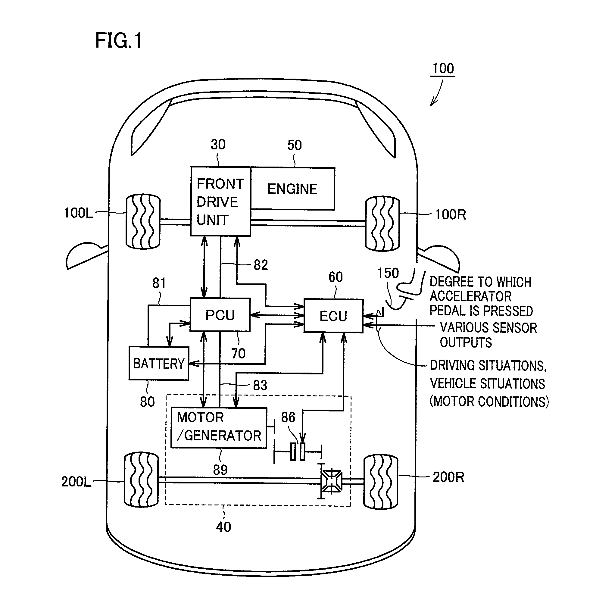
[0019]FIG. 1 is a block diagram illustrating a configuration of a motor vehicle including a drive apparatus for an electric vehicle according to one embodiment of the present invention. Referring to FIG. 1, a motor vehicle 100 according to the present embodiment includes front wheels 100L and 100R, rear wheels 200L and 200R, a front drive unit 30 for front-wheel drive, a rear drive unit 40 for rear-wheel drive, an engine 50, an ECU (Electrical Control Unit) 60, a PCU (Power Control Unit) 70, and a battery 80.

[0020]Rear drive unit 40 includes a rear motor / generator 89 that is a rotating electric machine used to drive rear wheels 200L and 200R, and a ...


PUM


Abstract

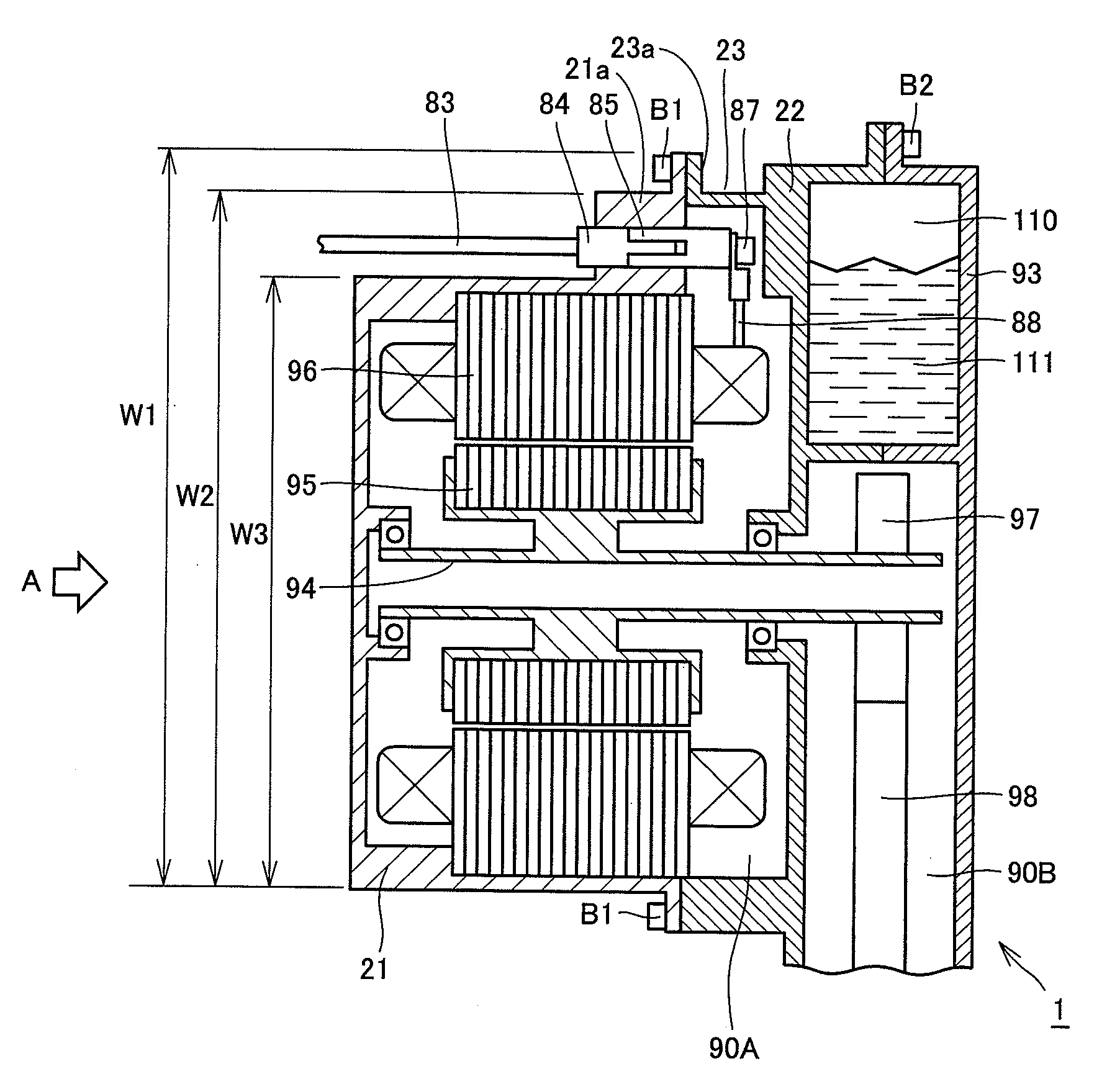
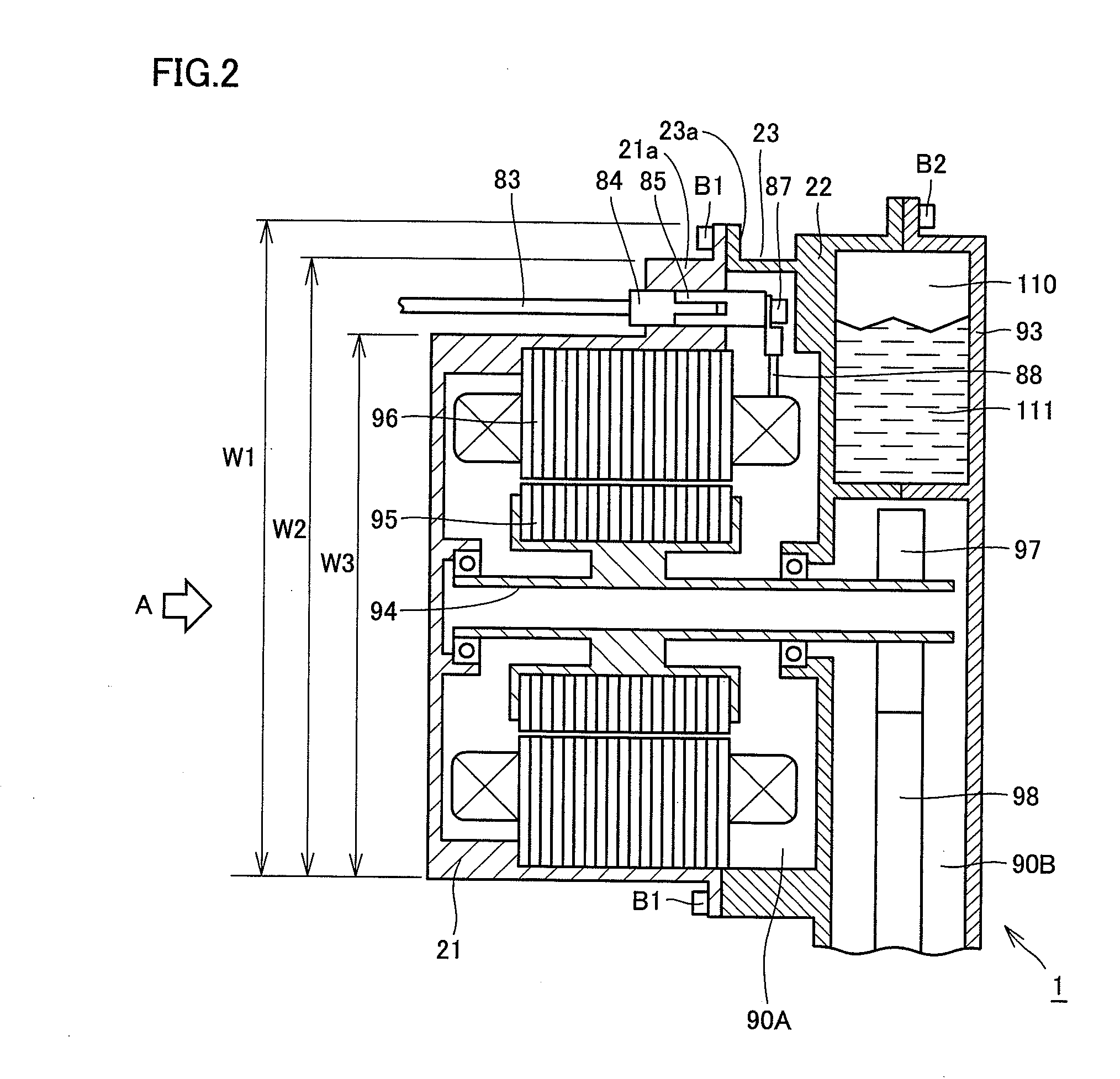
A drive device for an electric vehicle, having a structure where a stator is received inside a motor receiving cover to allow an inner cable, connected to the stator, to be led out to the transmission mechanism case side. This enables a projection to be provided on the transmission mechanism case side of the motor receiving cover, and also enables a female connector, connected to the inner cable, to be provided at the projection. The drive device for an electric vehicle has enhanced mountability.

Description

TECHNICAL FIELD [0001]The present invention relates to a drive apparatus for an electric vehicle, and in particular, to a drive apparatus for an electric vehicle driving an axle by a rotating electric machine.BACKGROUND ART [0002]A rotating electric machine having a stator and a rotor is conventionally known. A connecting terminal to which a power cable transmitting electric power from an external power source is connected is attached to the rotating electric machine. For example, in Japanese Patent Laying-Open No. 8-33262, a structure where a terminal is led out from the side of a motor cover is employed.[0003]FIG. 3 shows a structure where a power cable is led out from the upper surface of a rotating electric machine. FIG. 3 is a cross-sectional view taken along the direction of a rotation shaft of a motor 90 that is an example of the rotating electric machine. Motor 90 includes a rotation shaft 94, a rotor 95 fixed around this rotation shaft 94, and a stator 96 arranged to face t...

Claims


Application Information

Patent Timeline
IPC IPC(8): H02K11/00
CPCH02K3/50H02K5/225Y02T10/641Y02T10/6217B60L11/14Y02T10/7077B60L11/123B60L50/16B60L50/61Y02T10/62Y02T10/64Y02T10/70Y02T10/7072
Inventor MIURA, TETSUYAFUNATSU, WATARU
Owner TOYOTA JIDOSHA KK
Learn More