Centrifugal fan

A centrifugal fan and central axis technology, applied in cooling/ventilation devices, electromechanical devices, electrical components, etc., can solve the problem of increasing wind noise of centrifugal fans, and achieve the effect of suppressing wind noise

Inactive Publication Date: 2013-06-26
NIDEC CORP
View PDF7 Cites 4 Cited by
  • Summary
  • Abstract
  • Description
  • Claims
  • Application Information

AI Technical Summary

Problems solved by technology

However, if the circuit board is arranged in a wind tunnel, there is a problem that the wind impacts on the circuit board and the wind noise of the centrifugal fan increases.

Method used


Image

  • Centrifugal fan
  • Centrifugal fan
  • Centrifugal fan

Examples


no. 1 approach

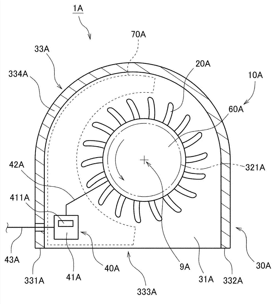
[0021] figure 1 It is a cross-sectional view of the fan 1A according to the first embodiment of the present invention. Such as figure 1 As shown, the centrifugal fan 1A has a motor 10A, an impeller 20A, a casing 30A, and a base plate 40A.

[0022] The motor 10A has a stationary part fixed to the housing 30A, and a rotating part 60A supported rotatably relative to the stationary part. The motor 10A rotates the rotating portion 60A around the central axis 9A extending up and down. The impeller 20A rotates together with the rotating part 60A. The casing 30A accommodates the rotating part 60A and the impeller 20A, and the casing 30A has an upper suction port 321 and an exhaust port 333A. The substrate 40A supplies drive current to the motor 10A.

[0023] The casing 30A has a bottom plate 31A, a top plate, and a side wall 33A. The bottom plate 31A extends in a direction substantially perpendicular to the central axis 9A on the lower side of the impeller 20A. Furthermore, the...

no. 2 approach

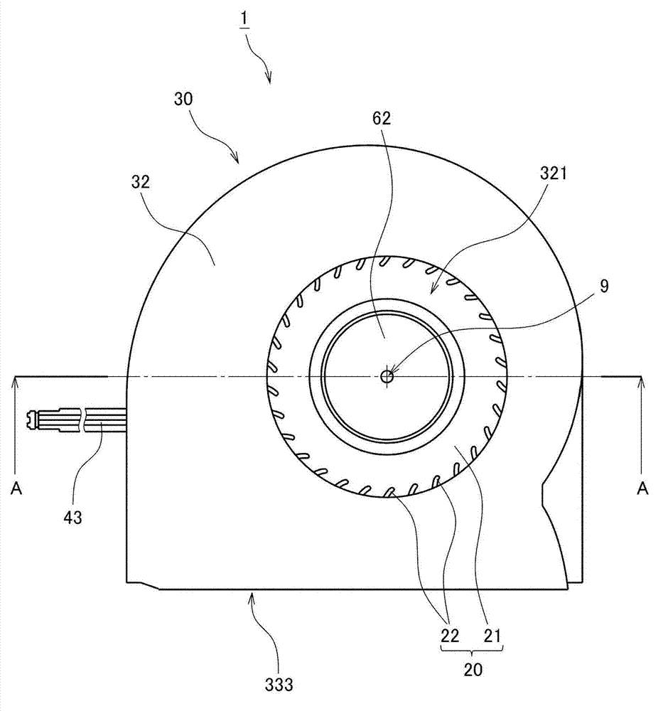
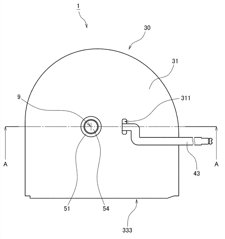
[0029] Next, a second embodiment of the present invention will be described. figure 2 It is a top view of the centrifugal fan 1 which concerns on 2nd Embodiment. image 3 It is the bottom view of the centrifugal fan 1. Figure 4 is a cross-sectional view of the centrifugal fan 1 . Figure 5 From Figure 2 to Figure 4 A vertical cross-sectional view of the centrifugal fan 1 observed at position A-A in .

[0030] This centrifugal fan 1 is installed in electronic equipment such as a notebook personal computer, and is used to cool the inside of the electronic equipment. Such as Figure 2 to Figure 5 As shown, the centrifugal fan 1 of this embodiment has a motor 10 , an impeller 20 , a casing 30 and a base plate 40 .

[0031] The motor 10 rotates the impeller 20 according to the drive current. Such as Figure 5 As shown, the motor 10 has a stationary part 50 fixed to the casing 30 , and a rotating part 60 rotatably supported relative to the stationary part 50 . The motor 1...


PUM


Abstract

A side wall of a centrifugal fan includes a gap expanding portion arranged to gradually expand a gap between an impeller and the side wall from an upstream end toward a downstream end with respect to a rotation direction of a rotating portion. In the centrifugal fan, an electronic component arranging portion of a board is arranged in an area surrounded by the gap expanding portion, the impeller, and an air outlet, and accordingly does not overlap with a motor or the impeller in an axial direction. The electronic component arranging portion is arranged in an area extending, in a circumferential direction about a central axis, from a position 180 degrees upstream from a middle of the air outlet downstream to the middle of the air outlet, that is, in an area where a wind channel has a large width.

Description

technical field [0001] The invention relates to a centrifugal fan. Background technique [0002] Conventionally, electronic devices such as personal computers have been equipped with centrifugal fans for internal cooling. When the centrifugal fan is driven, an airflow is generated inside the casing constituting the electronic device. Thereby, heat accumulation inside the case is suppressed. For example, Japanese Laid-Open Publication No. 2001-135964 describes the structure of a conventional centrifugal fan. [0003] A centrifugal fan has a circuit board for supplying drive current to the windings. Furthermore, in many conventional centrifugal fans, a magnetic sensor for detecting the rotation speed of the impeller is provided on the circuit board. Therefore, a circuit board including various electronic components is disposed near the rotating portion of the motor or the impeller. [0004] However, it is difficult to reduce the thickness of the centrifugal fan in the axi...

Claims


Application Information

Patent Timeline
Patent Type & Authority Applications(China)
IPC IPC(8): F04D25/08F04D29/28H02K9/06
CPCF04D25/08H02K21/22H02K7/14H02K9/06F04D17/16F04D29/5813F04D25/0633
Inventor 松叶直树丰岛弘祥依田圭人
Owner NIDEC CORP
Why Eureka
Try Eureka