
Vehicle drive device

A driving device, vehicle technology, applied in the direction of power plant, pneumatic power plant, electromechanical device, etc.

Pending Publication Date: 2022-03-04
AISIN CORP
View PDF2 Cites 0 Cited by
  • Summary
  • Abstract
  • Description
  • Claims
  • Application Information

AI Technical Summary

Problems solved by technology

In this way, in the vehicle drive device (1) of Patent Document 2, it is necessary to provide the rotation sensor (18) between the rotating body (97) and the fixed body (96), and between the fixed body (96) and the cylinder forming part. There is also a problem of increasing the size of the vehicle drive unit (1) in the radial direction (R) because a gap in the radial direction (R) is provided on both sides.

Method used


Image

  • Vehicle drive device
  • Vehicle drive device
  • Vehicle drive device

Examples


Embodiment Construction

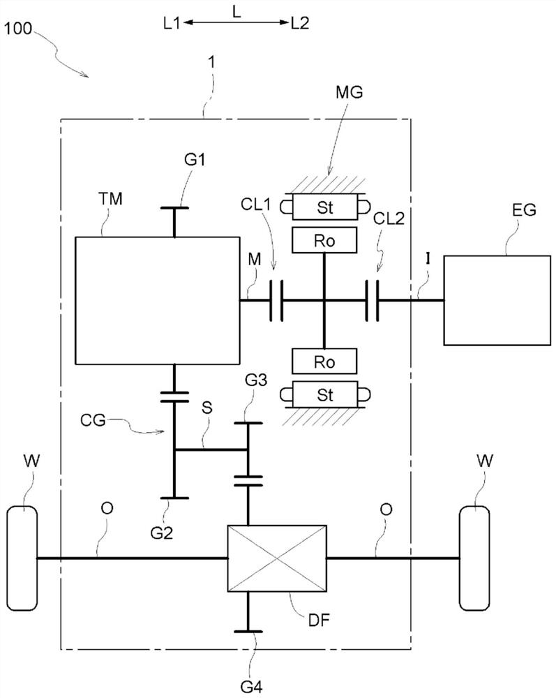
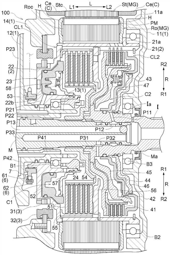
[0034] Hereinafter, a vehicle drive device 100 according to the embodiment will be described with reference to the drawings. Such as figure 1 As shown, the vehicle drive device 100 is a device for driving a vehicle (hybrid vehicle) including both an internal combustion engine EG and a rotary electric machine MG. Specifically, the vehicle drive device 100 is configured as a drive device for a single-motor parallel type hybrid vehicle.

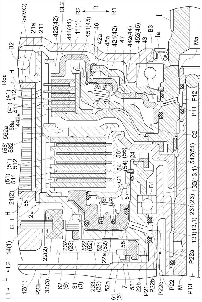
[0035] In the following description, unless otherwise specified, "axial direction L", "radial direction R", and "circumferential direction" are defined based on the rotation axis of the rotary electric machine MG. Furthermore, in the radial direction R, the rotation axis side of the rotary electric machine MG is referred to as "radially inner R1", and the opposite side thereof is referred to as "radially outer R2".

[0036] In addition, the direction of each component shows the direction in the state in which they were assembled in the vehicl...


PUM


Abstract

The rotor support member (2) is provided with: a cylindrical section (21) which is formed in a cylindrical shape extending in the axial direction (L) and supports the rotor (Ro) of the rotating electrical machine (MG); and a flange section (22) that is formed at a position adjacent to the first engagement device (CL1) on the first side (L1) in the axial direction and that is formed so as to extend in the radial direction (R) on the inside (R1) in the radial direction with respect to the cylindrical section (21), the flange section (22) being connected to the cylindrical section (21), and the flange section (22) being provided with a cylinder forming section (23) that protrudes toward the first side (L1) in the axial direction so as to form a cylinder section (C2) on which the first piston section (52) of the first engagement device (CL1) slides. A rotation sensor (3) is provided with: a rotating body (31) that is supported on the outer peripheral surface of a cylinder-forming section (23) on the outside (R2) in the radial direction; and a fixed body (32) disposed on the outside (R2) in the radial direction with respect to the rotating body (31).

Description

technical field [0001] The present invention relates to a drive device for a vehicle, comprising: a rotating electrical machine having a stator and a rotor disposed radially inward of the stator and functioning as a driving force source for a wheel; a rotor supporting member supporting the rotor; and a device for detecting the rotor. a rotating rotation sensor; and a first engagement device arranged radially inward with respect to the rotor. Background technique [0002] An example of such a vehicle drive device is disclosed in Patent Documents 1 and 2 below. Hereinafter, in the description of this background art, the reference numerals of the referenced patent documents are quoted in parentheses. [0003] In the vehicle drive device (100) of Patent Document 1, the first engagement device (4), the second engagement device (5) and the rotation sensor (37) are arranged in parallel in the axial direction. Therefore, the vehicle drive device (100) tends to increase in size in ...

Claims


Application Information

Patent Timeline
Patent Type & Authority Applications(China)
IPC IPC(8): B60K6/26B60K6/387B60K6/405B60K6/48B60K6/54B60L50/16F16D25/0638H02K5/173H02K7/108H02K7/18
CPCB60K6/387B60K6/405B60K6/54F16D25/0638H02K7/108Y02T10/62H02K7/08H02K7/116H02K5/1732B60Y2400/4244B60K2006/4825B60K6/48B60K6/547F16D25/10F16D2300/18H02K11/20B60K6/26
Inventor 森田桂史石山浩司
Owner AISIN CORP
Learn More