
sewing machine

A sewing machine and motor technology, applied in sewing machine components, sewing machines, sewing machine control devices, etc., can solve the problems of loss of component replacement and lack of versatility, and achieve the goal of suppressing axial size, improving versatility, and ensuring durability. Effect

Active Publication Date: 2018-02-16
JUKI CORP
View PDF8 Cites 0 Cited by
  • Summary
  • Abstract
  • Description
  • Claims
  • Application Information

AI Technical Summary

Problems solved by technology

As a result, the replaceability of parts is lost, and the versatility is lacking

Method used


Image

  • sewing machine
  • sewing machine
  • sewing machine

Examples


Embodiment Construction

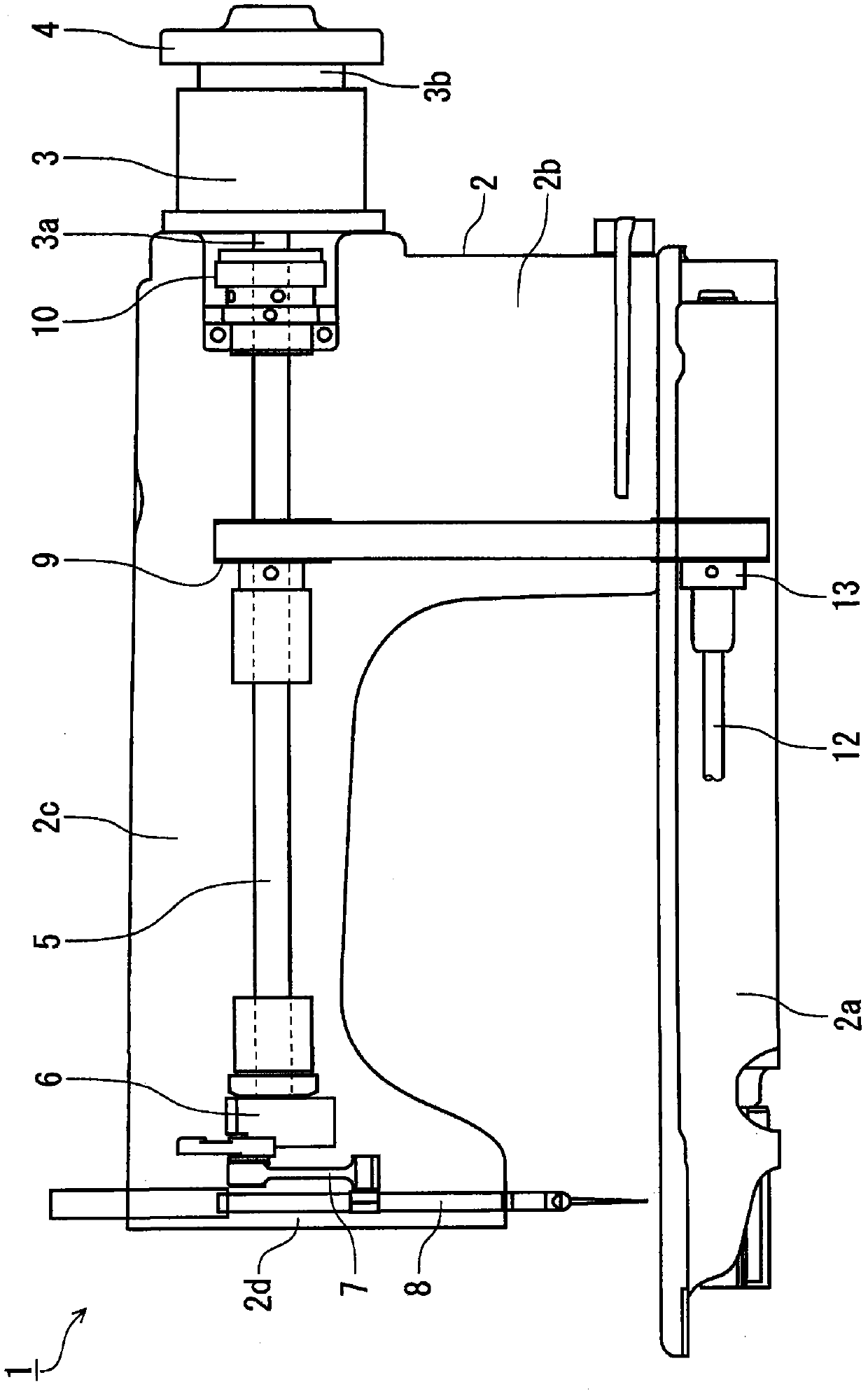
[0044] Below, refer to Figure 1 to Figure 5 , and the first embodiment of the present invention will be described.

[0045] Such as figure 1As shown, the sewing machine 1 has a sewing machine frame 2 . The sewing machine frame 2 has: a base portion 2a; a vertical body portion 2b, which is erected on the base portion 2a; an arm portion 2c, which is disposed substantially parallel to the base portion 2a from the upper portion of the vertical body portion 2b; and a head portion 2d, which It is arranged at the front end of the arm portion 2c.

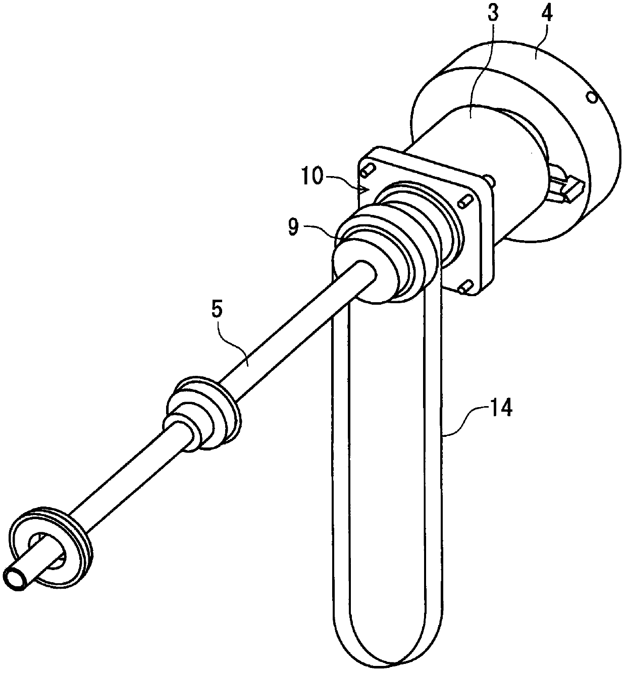
[0046] The electric motor 3 is disposed outside the upper portion of the vertical body portion 2b. The motor 3 has a pair of rotating shafts 3a, 3b protruding from both sides in the axial direction. The rotating shaft 3 a is connected to the upper shaft 5 , and the rotating shaft 3 b is connected to the flywheel 4 . The flywheel 4 is disposed outside the longitudinal body portion 2b. The outer periphery of the motor 3 is covered by ...


PUM


Abstract

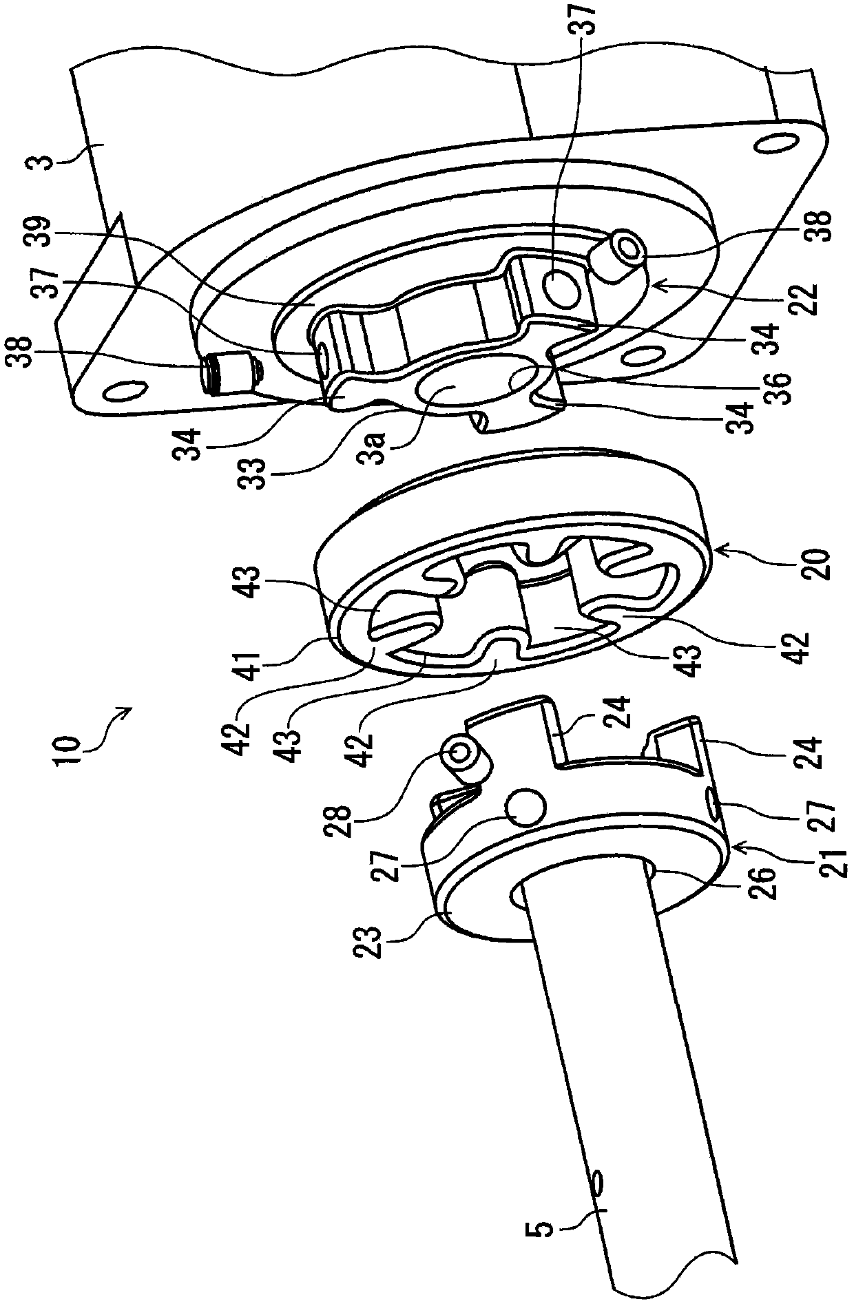
The present invention provides a sewing machine having a coupling connecting an upper shaft and a rotating shaft, and while ensuring the durability of the coupling, suppressing the axial dimension of the coupling, and improving the versatility of the coupling. The sewing machine has a coupling that connects the upper shaft and the rotating shaft of the motor. The coupling has: a first hub, which is fixed on one of the upper shaft and the rotating shaft, and has a first annular portion, a plurality of first engaging protrusions, and a first insertion hole; a second hub, It is fixed to the other of the upper shaft and the rotating shaft, and has a second annular portion, a plurality of second engagement protrusions, a second insertion hole, and a connecting member formed of an elastic material. The first hub and the second hub are fitted with the connecting member so as to sandwich the engaging portion of the connecting member between the first engaging protrusion and the second engaging protrusion in the circumferential direction. The connection member has an annular portion formed in an annular shape. The plurality of engaging portions protrude radially inward from the inner peripheral surface of the annular portion. The second annular portion and the second engagement convex portion are fitted inside the annular portion and accommodated.

Description

technical field [0001] The present invention relates to a sewing machine having a coupling for connecting two shafts. Background technique [0002] To the upper shaft of the sewing machine, the rotating shaft of the electric motor or the rotating shaft rotated by the transmission of the rotational force of the electric motor is connected via a coupling. [0003] Such as Figure 13 As shown, the conventional coupling 71 has: hubs 72, 73 fixed on the upper shaft and the rotating shaft, respectively; [0004] The hubs 72 , 73 have engagement protrusions 75 , 76 on opposing surfaces, and are provided at intervals in the circumferential direction. Insertion holes 77, 78 are formed at the center of the hubs 72, 73, which allow the upper shaft or the rotation shaft to be inserted. The hubs 72 , 73 have threaded holes 81 , 82 formed extending radially from the outer peripheral surfaces of the hubs 72 , 73 to the insertion holes 77 , 78 . Screws are screwed into the screw holes 81...

Claims


Application Information

Patent Timeline
Patent Type & Authority Patents(China)
IPC IPC(8): D05B69/00D05B69/30
Inventor 尾崎健治白石正金子笃
Owner JUKI CORP
Learn More