
LED drive circuit

A technology of LED drive and LED light source, applied in the field of lighting, can solve the problems of high cost, easy damage, complex circuit, etc., and achieve the effect of avoiding light decay acceleration or burning out

Active Publication Date: 2012-10-17
OCEANS KING LIGHTING SCI&TECH CO LTD +1
View PDF7 Cites 20 Cited by
  • Summary
  • Abstract
  • Description
  • Claims
  • Application Information

AI Technical Summary

Problems solved by technology

At present, DC-DC chopping technology is used to drive LED in low-voltage places. It has the advantages of low power consumption, high efficiency, stability and reliability, small size per unit power, light weight, etc., but its cost is high, the circuit is complicated, and easy to use. Damage, strong high-frequency interference and other shortcomings, which bring inconvenience to users

Method used


Image

  • LED drive circuit
  • LED drive circuit

Examples


Embodiment Construction

[0027] In order to make the object, technical solution and advantages of the present invention more clear, the LED driving circuit of the present invention will be further described in detail below in conjunction with the accompanying drawings and embodiments. It should be understood that the specific embodiments described here are only used to explain the present invention, not to limit the present invention.

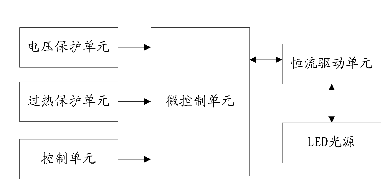
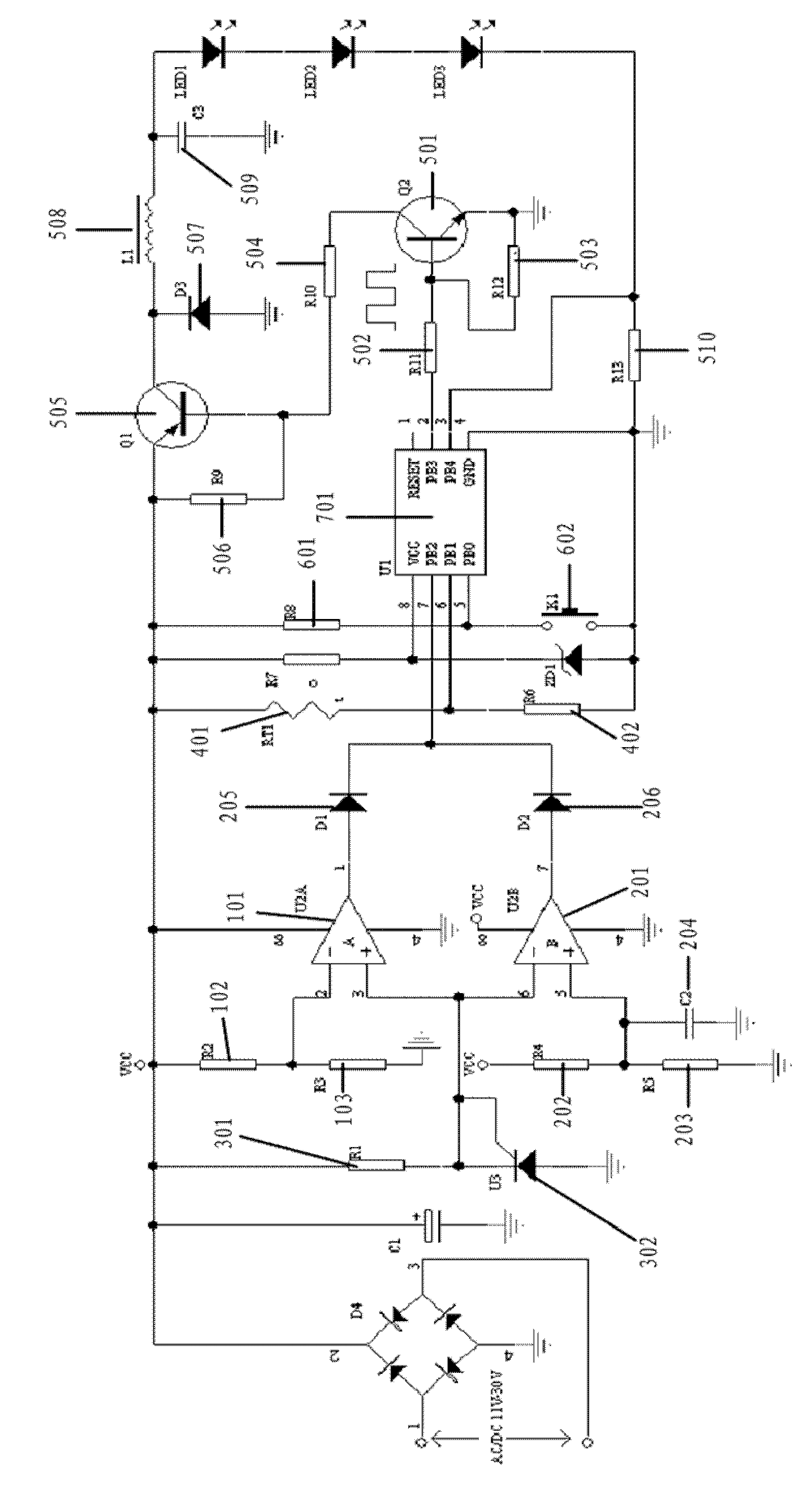
[0028] The LED driving circuit of the present invention, such as figure 1 As shown, it includes a Micro Control Unit (MCU for short), a voltage protection unit and an LED light source; when the input voltage of the LED driving circuit is between the rated minimum voltage and the rated maximum voltage, the LED light source works normally; If the rated minimum voltage is 11 volts, the rated maximum voltage is 30 volts;

[0029] The voltage protection unit includes an undervoltage protection module, an overvoltage protection module and a reference voltage stabilizing mod...


PUM


Abstract

The present invention relates to an LED drive circuit which includes a micro-control unit, a voltage protection unit and an LED light source. The voltage protection unit includes an under-voltage protection module, an overvoltage protection module and a reference voltage module. The under-voltage protection module includes a detection voltage input terminal and a reference minimum voltage input terminal. The overvoltage protection module comprises a detection voltage input and a reference maximum voltage input terminal. The reference voltage module provides reference minimum voltage to the under-voltage protection module and provides reference maximum voltage to the overvoltage protection module. The under-voltage protection module and a reference voltage regulation module are set, thus when input voltage is lower than rated minimum voltage, detection voltage is lower than the reference minimum voltage, and the LED light source is turned off. The overvoltage protection module and the reference voltage regulation module, thus when the input voltage is higher than rated maximum voltage, the detection voltage is higher than the reference maximum voltage, and the LED light source is turned off. The LED drive circuit can maintain a constant current characteristic and has the protection of under-voltage, overvoltage and overheating.

Description

technical field [0001] The invention relates to the lighting field, in particular to an LED driving circuit. Background technique [0002] With the continuous development of science and technology, LED, as a new type of light source, has the characteristics of high luminous efficiency, high efficiency and energy saving, long life, low voltage controllable, etc., and is widely used in indoor and outdoor lighting in various fields. kind of LED driver circuit. At present, DC-DC chopping technology is used to drive LED in low-voltage places. It has the advantages of low power consumption, high efficiency, stability and reliability, small size per unit power, light weight, etc., but its cost is high, the circuit is complicated, and easy to use. Damage, strong high-frequency interference and other shortcomings have brought inconvenience to users. In the application, the LED drive circuit needs to maintain the constant current characteristic as much as possible, that is, when the...

Claims


Application Information

Patent Timeline
IPC IPC(8): H05B37/02H02H3/24H02H3/20
CPCH05B47/24Y02B20/30H05B45/56
Inventor 周明杰黄柯青
Owner OCEANS KING LIGHTING SCI&TECH CO LTD
Learn More