Coupling system between waste heat generating device and waste heat absorbing device

A coupling system and generating device technology, applied in the field of coupling systems, can solve problems such as poor contact, structural space limitations, and difficult to fix components in the central area, and achieve the effect of small assembly investment and helpful assembly

Inactive Publication Date: 2015-08-19
SIEMENS AG
View PDF3 Cites 0 Cited by
  • Summary
  • Abstract
  • Description
  • Claims
  • Application Information

AI Technical Summary

Problems solved by technology

For example, the design of the waste heat generating device and / or the waste heat absorbing device often results in a limited installation space and / or poor accessibility, making it difficult to arrange the fastening element in the central area of ​​the contact surface

Method used


Image

  • Coupling system between waste heat generating device and waste heat absorbing device
  • Coupling system between waste heat generating device and waste heat absorbing device
  • Coupling system between waste heat generating device and waste heat absorbing device

Examples


Embodiment Construction

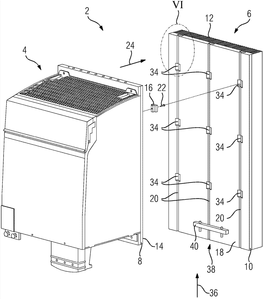
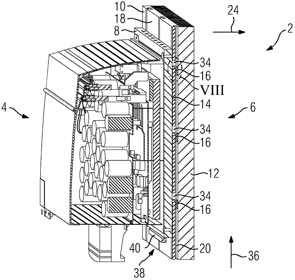
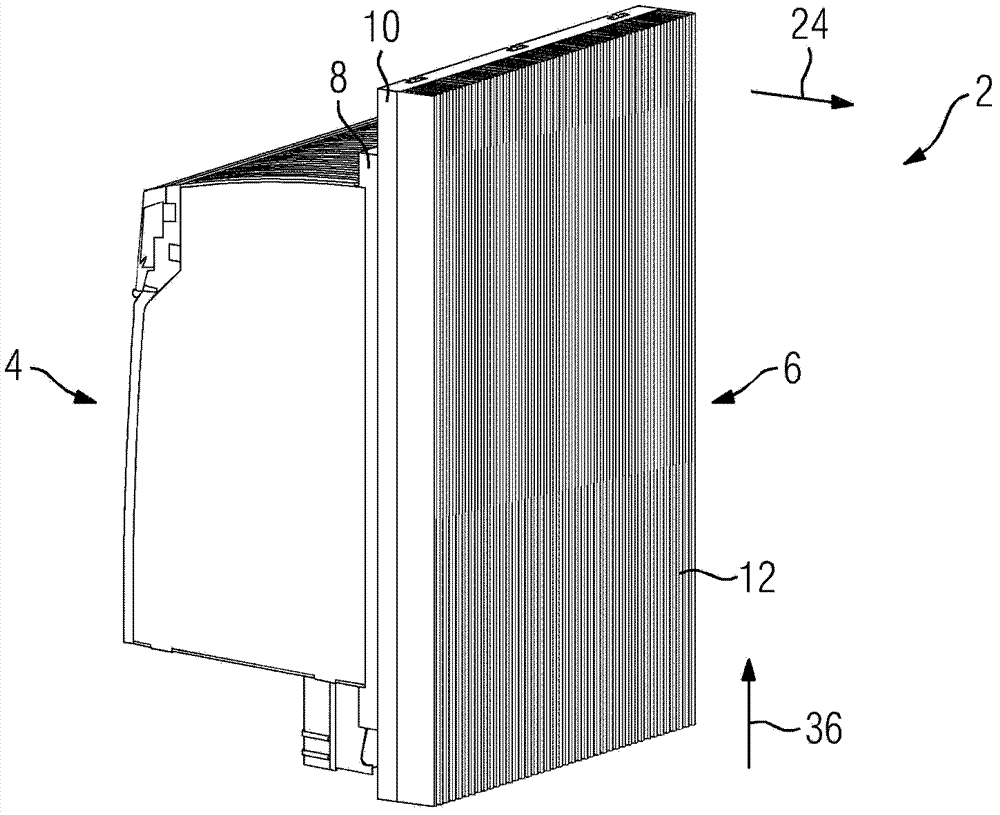
[0035] described below, in figure 1A coupling system 2 of the kind depicted in the exploded view of is used in the exemplary embodiment as a thermal interface between the converter 4 and the cooling body 6 . The converter 4 serves here as waste heat generator and has a square first contact plate 8 made of aluminum. The cooling body 6 , which is used here by way of example as waste heat absorber, likewise has a square second contact plate 10 made of aluminum. In the assembled state of the coupling system 2, in the corresponding view figure 2 and image 3 In , the two contact plates 8 , 10 are placed in parallel planes to each other for heat exchange purposes. The two contact plates 8 , 10 are thus both components of the converter 4 or heat sink 6 and part of the coupling system 2 . A plurality of groove-spring connections are provided for connecting and tensioning the two contact plates 8 , 10 , so that in the exemplary embodiment the coupling system 2 is provided by the t...


PUM


Abstract

The system (2) has two bodies (8, 10) having two contact surfaces (14, 18), where the contact surfaces lies opposite to each other for a heat exchanger. A nut-spring connector is provided with a nut block (16) and a nut (20) for the connection and clamping of the contact surfaces, where the nut extends in a longitudinal direction (36). The nut and nut block are formed such that a pressing force is applied in a direction of a surface normal (24) of the contact surfaces when nut and nut block are connected together. The nut block is uniformly arranged on the contact surfaces.

Description

technical field [0001] The invention relates to a coupling system as thermal interface between a waste heat generating device (in particular a converter) and a waste heat absorbing device (especially a cooling body), the coupling system comprising a first body with a first contact surface And a second body with a second contact surface, wherein the two contact surfaces bear against each other for heat exchange purposes. Background technique [0002] The device-specific and operating state-dependent power losses of technical devices (e.g. electronic modules) often lead to overheating in the device on the one hand and in the surrounding environment on the other hand, which have a negative impact on the functioning of the device. Adversely affect safety and / or life expectancy. Therefore, it is often necessary to dissipate and conduct away the waste heat generated or lost from the device. For this purpose, the device as waste heat generating device is connected or coupled toge...

Claims


Application Information

Patent Timeline
Patent Type & Authority Patents(China)
IPC IPC(8): H05K7/20
CPCH05K7/20418H05K7/209
Inventor 汉斯·克瑙尔
Owner SIEMENS AG
Why Eureka
Try Eureka