Manufacturing method of rare earth-iron ring magnet with continuous orientation controlled anisotropy

An anisotropic, ring-shaped magnet technology, applied in the manufacture of inductors/transformers/magnets, permanent magnets, permanent magnets, etc., can solve problems such as deterioration, shortage, and sacrifice of motor torque density, and achieve resource saving effects

Active Publication Date: 2012-10-17
PANASONIC CORP
View PDF4 Cites 6 Cited by
  • Summary
  • Abstract
  • Description
  • Claims
  • Application Information

AI Technical Summary

Problems solved by technology

Therefore, using Figure 11A , Figure 11B and Figure 11C The shown prior art cogging torque reduction method suffers from the problem of sacrificing the increase in the torque density of the motor due to the increase in the energy density (BH)max of the magnet
That is, since 1985, R.W.Lee et al. used energy density (BH)max as 111kJ / m 3 The strip fabrication energy density (BH)max is 72kJ / m 3 The isotropic Nd of 2 Fe 14 Although more than 20 years have passed since Class B bonded magnets, the progress in energy density (BH)max is less than 10kJ / m 3
However, the opposite will result in increased cogging torque
Moreover, as far as the existing radially anisotropic ring magnet is concerned, when its inner and outer diameters are reduced, even if the core of the ring cavity (ring cavity) is made to repel the external magnetic field Hex to generate a radially oriented magnetic field, due to its magnetic flux leakage The increase of the amount will also lead to the deterioration of the reduction degree of the energy density (BH)max

Method used


Image

  • Manufacturing method of rare earth-iron ring magnet with continuous orientation controlled anisotropy
  • Manufacturing method of rare earth-iron ring magnet with continuous orientation controlled anisotropy
  • Manufacturing method of rare earth-iron ring magnet with continuous orientation controlled anisotropy

Examples


Embodiment approach

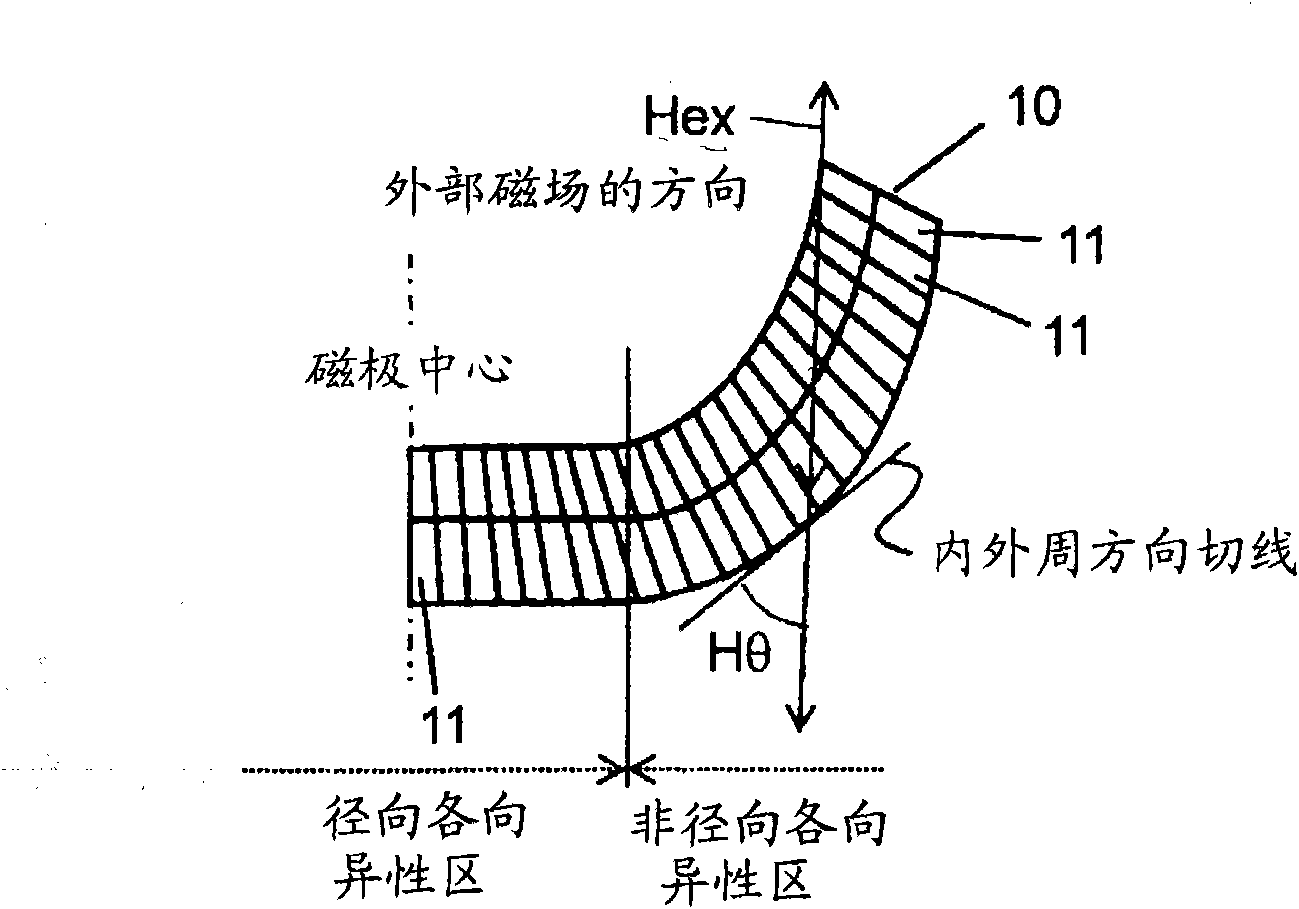
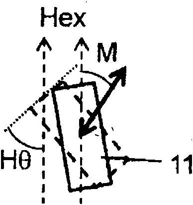
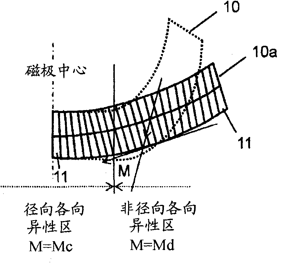
[0079] In the present invention, the following two steps must be performed. One is the step of creating a segment in which the anisotropic direction continuously changes from a direction perpendicular to the plane to in-plane using a uniform magnetic field that maintains a constant direction while mechanically designing the magnet. That is, in the produced segment, the anisotropy direction continuously changes from the direction perpendicular to the surface receiving the uniform magnetic field to the direction in which the surface receiving the uniform magnetic field extends. Another step that must be performed is to arrange a plurality of the above-mentioned segments on the circumference, extrude it into a ring shape from the thrust direction end face of one side of the segment using the rheology based on the viscous deformation of the segment, and then from the segment's Compression steps are performed on both end faces in the thrust direction.

[0080] The manufacturing st...

Embodiment

[0107] Hereinafter, the rare earth-iron ring magnet with continuously controlled anisotropy direction of the present invention will be described in more detail with reference to an embodiment of an 8-pole, 12-slot surface magnet synchronous motor (SPMSM). However, the present invention is not limited to this embodiment.

[0108] first, Figure 5 To show the density of the present invention 6.01Mg / m 3 A diagram of a scanning electron microscope (SEM) photograph of the macrostructure of a magnet. where the anisotropy Sm 2 Fe 17 N 3 Rare earth-like magnet materials and anisotropic Nd 2 Fe 14 The B-type rare earth-iron magnet material and the thermosetting resin composition are simultaneously heated at 160°C, applying an orientation magnetic field so that the uniform external magnetic field is 1.4MA / m, and performing compression molding under a pressure of 20-50MPa to form fragment. Here, the anisotropy Sm 2 Fe 17 N 3 Rare earth-like magnet material with a particle size...


PUM

PropertyMeasurementUnit
energy densityaaaaaaaaaa
diameteraaaaaaaaaa
thicknessaaaaaaaaaa

Abstract

The essential processes of this method include: a process for manufacturing segments, an anisotropic direction of which is continuously changed from a direction perpendicular to a surface to inside the surface by a uniform magnetic field maintained in a constant direction; and a process for arranging a plurality of the segments on a circumference, extruding the segments in a ring shape by rheology based on viscous deformation of the segments from one thrust direction end surface of the segments, and compressing the segments from both end surfaces in the thrust direction of the segments. In a ring magnet in which the anisotropic orientation is continuously controlled, the generation source of the static magnetic field has an energy density (BH) max >= 160 to 180 kJ / m<3>.

Description

technical field [0001] The present invention relates to a rare earth-iron having a radially anisotropic region at the center of a magnetic pole and a non-radial magnetically anisotropic region between magnetic poles, which does not degrade magnetic properties even when formed into a small diameter. A method of manufacturing a quasi-ring magnet. More specifically, the present invention relates to a method for manufacturing a rare-earth-iron-based ring magnet with continuously controlled anisotropy direction, which is widely used as a home appliance, an air conditioner, etc. High-performance permanent magnet motors that have a major impact on power saving, energy saving, miniaturization, and quietness of magnet-type motors of about 50W or less for various drive sources such as equipment and information equipment. Background technique [0002] The motor is regarded as a kind of rotor, shaft, bearing, stator, etc. manufactured by high-precision machining of various materials su...

Claims


Application Information

Patent Timeline
Patent Type & Authority Applications(China)
IPC IPC(8): H02K15/03H01F7/02H01F13/00H01F41/02H01F1/08
CPCH02K15/03H02K1/278H01F1/0578H01F1/059H01F41/028Y10T29/49078Y10T29/49803Y10T29/49075Y10T29/49805Y10T29/49009Y10T29/49069
Inventor 山下文敏河村清美冈田幸弘村上浩
Owner PANASONIC CORP
Why Eureka
Try Eureka