
Weft insertion device of circular loom

A technology of weft insertion device and circular loom, applied in the field of machinery, can solve problems such as inability to weave, and achieve the effect of eliminating the phenomenon of strong extrusion

Active Publication Date: 2012-10-24
PACIFIC MECHATRONIC GRP
View PDF13 Cites 0 Cited by
  • Summary
  • Abstract
  • Description
  • Claims
  • Application Information

AI Technical Summary

Problems solved by technology

Therefore, when the circular loom weaves materials with low strength, it cannot weave

Method used


Image

  • Weft insertion device of circular loom

Examples


Embodiment 1

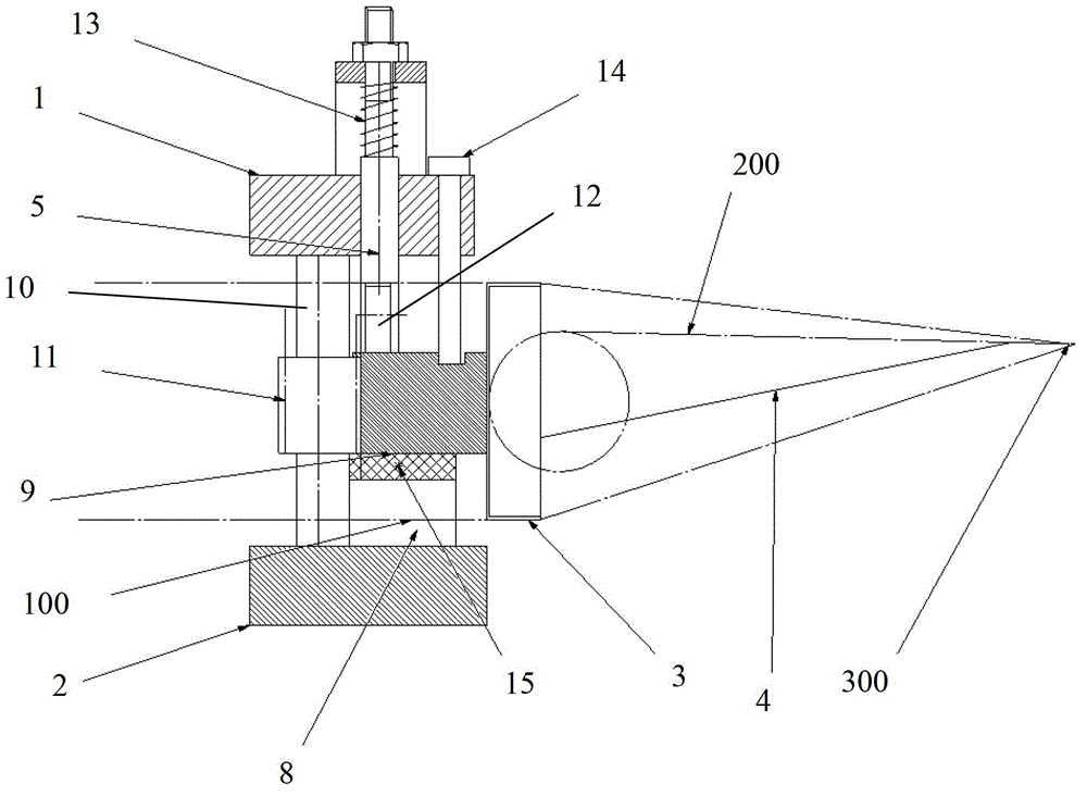
[0010] like figure 1 As shown, a weft insertion device of a circular loom according to the present invention includes an upper ring 1, a lower ring 2, a bobbin case 3 and a warp dividing sheet 8, wherein the upper ring 1 and the lower ring 2 are up and down Arranged in parallel, the bobbin case 3 is arranged between the upper ring 1 and the lower ring 2, and the warp dividing sheet 8 is arranged between the upper ring 1 and the lower ring 2 and supports the upper ring 1 and the lower ring 2, the shuttle The back of the shell 3 is provided with a rack 9, a gear shaft 10 is provided between the upper ring 1 and the lower ring 2, and the gear shaft 10 is provided with a gear 11, and the gear 11 meshes with the rack 9 , include a boss plane in the divided warp sheet 8, a nylon strip 15 is arranged between the bottom surface of the rack 9 and the boss plane, the boss plane is parallel to the plane of the upper ring 1 and the lower ring 2, the bottom surface of the nylon strip 15 A...


PUM


Abstract

The invention discloses a weft insertion device of a circular loom, which comprises an upper ring, a lower ring, a bobbin case and a leasing plate. The bobbin case is arranged between the upper ring and the lower ring; the leasing plate supports the upper ring and the lower ring; a rack is arranged on the backside of the bobbin case; a gear shaft is arranged between the upper ring and the lower ring and a gear wheel meshed with the rack is arranged on the gear shaft; the leasing plate comprises a convex plane; the underside of the rack and the convex plane form a sliding pair; a guide device is arranged between the rack and the upper ring; a pinch roller column is arranged in the upper ring and the lower end of the pinch roller column is connected with a pinch roller; and the pinch rolleris biased on the face of the rack by a spring to enable the rack to be tightly attached on the convex plane of the leasing plate all the time so as to ensure stable movement of a shuttle. After beingshed, warps pass through the area between the upper and lower rings along the upper and lower edges of the bobbin case, and the gear wheel drives the bobbin case to move through the rack to realize weft insertion. With the weft insertion device, the warps can not be extruded by brute force, the weft insertion device can be suitable for yarns with weaker brute force and can be used for weaving fabrics with smaller diameters.

Description

Technical field: [0001] The invention relates to the field of machinery, in particular to textile machinery, in particular to a circular loom, and in particular to a weft insertion device for a circular loom. Background technique: [0002] In the circular loom of the prior art, the power is transmitted from the center of the circle of the circular loom to push the weft yarn shuttle to pass through the warp yarn intersection opening to realize the weft insertion action. The weft shuttle moves on guide rails in the upper and lower rings with the help of its side and bottom rollers, thus compressing the warp threads. And, due to the promotion of the outside rollers, the lower warp threads are squeezed again at the push rollers. Therefore, when circular looms weave materials with low strength, they cannot be woven. Invention content: [0003] The object of the present invention is to provide a weft insertion device of a circular loom, which solves the technical problem of t...

Claims


Application Information

Patent Timeline
IPC IPC(8): D03D49/26D03D37/00
Inventor 王顺弟周骏彦苏继伟凌洁
Owner PACIFIC MECHATRONIC GRP
Learn More