Mixing device for vehicle engine exhaust gas recirculation (EGR)

A technology for exhaust gas recirculation and vehicle engines, which is applied in the direction of exhaust gas recirculation, engine components, combustion engines, etc., can solve the problems of reducing exhaust gas, intake air mixing uniformity, etc., and achieves small intake pressure loss and enhanced stability Effect

Active Publication Date: 2012-10-24
DONGFENG MOTOR CORP HUBEI
View PDF7 Cites 10 Cited by
  • Summary
  • Abstract
  • Description
  • Claims
  • Application Information

AI Technical Summary

Problems solved by technology

[0006] First of all, the exhaust pipe in this invention is not perpendicular to the diversion shell, and there is an acute angle between the exhaust pipe and the diversion shell. The existence of this angle will cause the exhaust gas to flow in an oblique direction in the intake pipe, thereby reducing the The uniformity of exhaust gas and intake air mixing;

Method used


Image

  • Mixing device for vehicle engine exhaust gas recirculation (EGR)
  • Mixing device for vehicle engine exhaust gas recirculation (EGR)
  • Mixing device for vehicle engine exhaust gas recirculation (EGR)

Examples


Embodiment 1

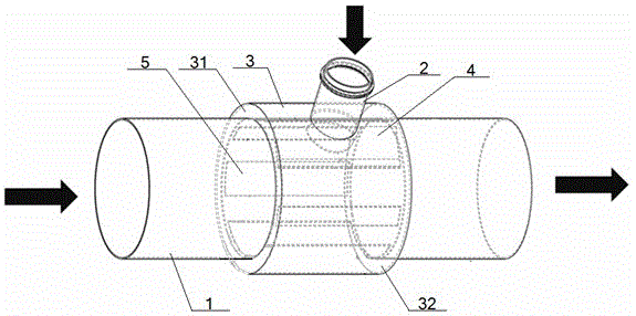
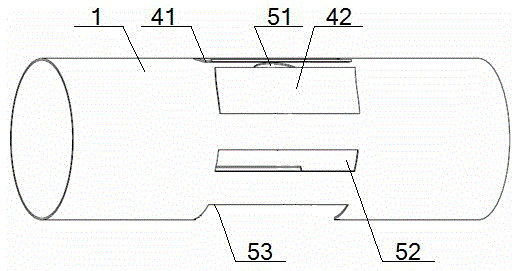
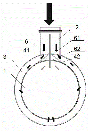
[0043] see figure 1 – image 3 , a mixing device for exhaust gas recirculation (EGR) of a vehicle engine, comprising an intake pipe 1, an exhaust pipe 2, a diversion shell 3 and an exhaust gas diversion device, and the exhaust gas diversion device includes a deflector 4 and an exhaust gas Channel 5, the deflector 4 includes a symmetrically arranged first deflector 41 and a second deflector 42, the first deflector 41 and the second deflector 42 are arc-shaped, and the first deflector The radians of the plate 41 and the second deflector 42 are consistent, and the exhaust gas channel 5 includes a front exhaust gas channel 51, a side exhaust gas channel 52 and a rear exhaust gas channel 53;

[0044] The side of the diversion shell 3 is vertically connected with the exhaust pipe 2, and the inside of the diversion shell 3 is provided with a coaxial air intake pipe 1. The outer walls are connected, one end of the No. 1 deflector 41 and the No. 2 deflector 42 are all connected with ...


PUM


Abstract

The invention discloses a mixing device for a vehicle engine exhaust gas recirculation (EGR). The mixing device comprises a gas inlet pipe, an exhaust gas pipe, a flow guide shell and an exhaust gas flow guide device, wherein the exhaust gas flow guide device comprises a first flow guide plate, a second flow guide plate, a front exhaust gas passage, a lateral exhaust gas passage and a back exhaust gas passage; one end of the first flow guide plate and one end of the second flow guide plate are connected with the outer wall of the gas inlet pipe, and the other ends of the first flow guide plate and the second flow guide plate are connected with the inner wall of the flow guide shell; a small cavity port of the gas inlet cavity between the first flow guide plate and the second flow guide plate is communicated with the exhaust gas pipe, and a large cavity port of the gas inlet cavity is opposite to the front exhaust gas passage; a part of the gas inlet pipe opposite to the front exhaust gas passage is provided with the back exhaust gas passage; the lateral exhaust gas passage is formed between the front exhaust gas passage and the back exhaust gas passage; the front exhaust gas passage is smaller than the lateral exhaust gas passage; and the lateral exhaust gas passage is smaller than the back exhaust gas passage. According to the mixing device, the uniformity of mixing of exhaust gas and inlet gas can be improved, the stability of operation of an engine is enhanced, the gas inlet pressure loss is small, the structure is simple, and the manufacturing is convenient.

Description

technical field [0001] The invention relates to a gas mixing device, in particular to a mixing device for vehicle engine exhaust gas recirculation (EGR), which is particularly suitable for improving the uniformity of exhaust gas and intake air mixing. Background technique [0002] At present, exhaust gas recirculation EGR (Exhaust Gas Recirculation) is to reduce the harmful emission of NO from vehicle engines. X As one of the effective measures, EGR technology has been widely used in vehicle engines at home and abroad. As the requirements of vehicle emission indicators become more and more stringent, more and more attention is paid to the research of EGR technology. [0003] Exhaust gas recirculation is to send part of the exhaust gas discharged from the engine back to the intake pipe according to the temperature and load of the engine under the premise of ensuring that the power performance of the engine is not significantly reduced, and then enter the cylinder again after ...

Claims


Application Information

Patent Timeline
Patent Type & Authority Applications(China)
IPC IPC(8): F02M25/07F02M26/19
CPCY02T10/121Y02T10/12
Inventor 陈镇殷勇余建华阳松林
Owner DONGFENG MOTOR CORP HUBEI
Why Eureka
Try Eureka