
Compound vacuum gauge calibration system and method

A calibration method and composite technology, applied in the field of measurement, can solve the problems of high production cost and large vacuum gauge calibration system, and achieve the effect of low cost, small weight and volume

Inactive Publication Date: 2012-10-24
卢耀文
View PDF3 Cites 23 Cited by
  • Summary
  • Abstract
  • Description
  • Claims
  • Application Information

AI Technical Summary

Problems solved by technology

[0004] The purpose of the present invention is to solve the problem of large vacuum gauge calibration system and high production cost in the prior art, and propose a composite vacuum gauge calibration system and method

Method used


Image

  • Compound vacuum gauge calibration system and method
  • Compound vacuum gauge calibration system and method

Examples


Embodiment 1

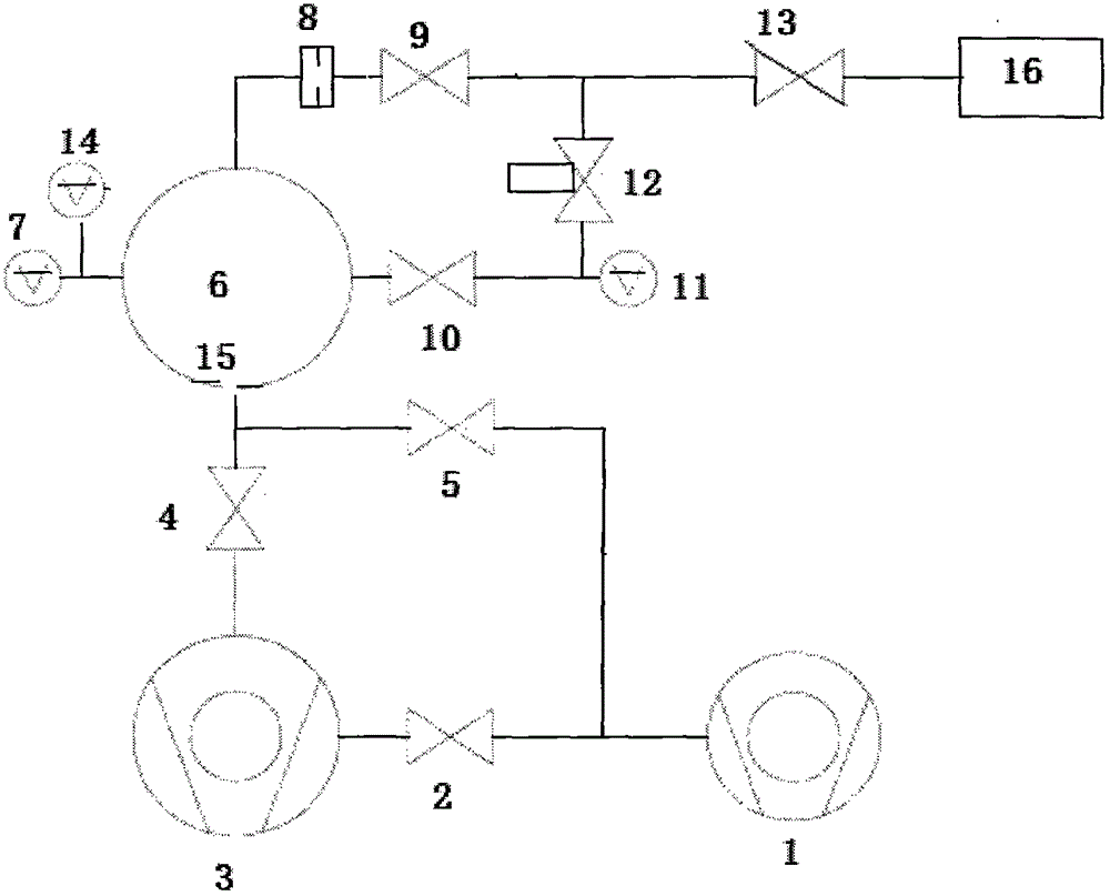
[0029] Such as figure 1 As shown, the compound vacuum gauge calibration system and method described in this embodiment includes: the system includes: a mechanical pump 1, a molecular pump 3, a first vacuum valve 2, a second vacuum valve 4, and a third vacuum valve 5. The fourth vacuum valve 9, the fifth vacuum valve 10, the sixth vacuum valve 12, the seventh vacuum valve 13, the vacuum gauge 7, the capacitance film gauge 11, the third vacuum gauge 14, the calibration chamber 6, the first vacuum valve with a diameter of 2um A small hole 8, a second small hole 15 with a diameter of 11mm, and an air source 16, wherein the valve 12 is a three-way valve with a 1mL sampling chamber.

[0030] The connection relationship is as follows: the mechanical pump 1 is connected to the first vacuum valve 2 at the same time; the other end of the first vacuum valve 2 is connected to the molecular pump 3; one end of the second vacuum valve 4 is connected to the molecular pump 3, and the other end...


PUM

PropertyMeasurementUnit
correction factoraaaaaaaaaa

Abstract

The invention discloses a compound vacuum gauge calibration system and method, belonging to the technical field of measurement. The compound vacuum gauge calibration system disclosed by the invention comprises a mechanical pump, a molecular pump, a first vacuum valve, a second vacuum valve, a third vacuum valve, a fourth vacuum valve, a fifth vacuum valve, a sixth vacuum valve, a seventh vacuum valve, a vacuum gauge, a capacitance diaphragm gauge, a third vacuum gauge, a calibration chamber, a first small hole, a second small hole and an air source. The invention further discloses a compound vacuum gauge calibration method; a capacitance diaphragm gauge of which the full range is 1000 Torr is adopted as reference standard; the direct comparison method is adopted to realize the calibration within the range of 10<5> to 100 Pa; the expansion method is adopted to realize the calibration within the range of 100 to 10<-3> Pa; and the dynamic flow conductance method is adopted to realize the calibration within the range of 10<-4> to 10<-6> Pa. The compound vacuum gauge calibration system disclosed by the invention has the characteristics of low cost, small weight and size, portability, and the like.

Description

technical field [0001] The invention relates to a composite vacuum gauge calibration system and method, belonging to the technical field of measurement. Background technique [0002] With the development of science and technology, industries such as aerospace, surface, microelectronics, solar energy, and optoelectronics have put forward higher requirements for vacuum calibration testing. It is necessary to test various vacuum environments and complete the calibration of vacuum gauges on site. And the document "Development of Vacuum Measurement Standard Device by Comparison Method", "Aerospace Measurement Technology" No. 66, No. 6, 1992, Page 70-73", introduces the calibration method and calibration system of the comparison method vacuum gauge , but the calibration range is 10 5 ~10 -4 Pa, and at 10 -1 ~10 -4 In the Pa pressure range, the magnetic levitation rotor gauge is used for measurement. The lower limit of this measurement method is limited by the lower limit of th...

Claims


Application Information

Patent Timeline
Patent Type & Authority Applications(China)
IPC IPC(8): G01L27/00
Inventor 卢耀文
Owner 卢耀文
Learn More