Radar sensor, automobile and target direction identification method
A radar sensor and target technology, applied in the field of radar sensors, can solve the problems of increasing the complexity of the optical receiving unit of the radar sensor in the number of photodetectors, increasing the system cost, and the inability of a single photodetector to identify the target, and achieving easy implementation and promotion. Application, lower hardware cost, simple and reliable identification method
- Summary
- Abstract
- Description
- Claims
- Application Information
AI Technical Summary
Problems solved by technology
Method used
Image

Examples
Embodiment 1
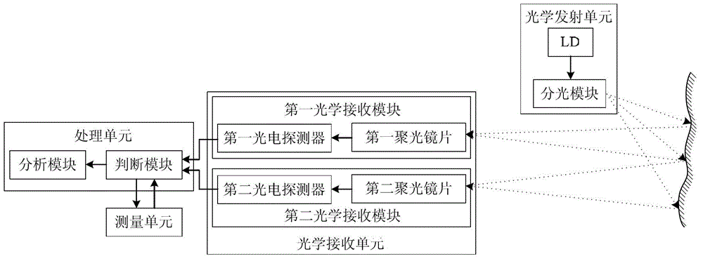
[0052] like figure 1 As shown, in this embodiment, the radar sensor includes an optical transmitting unit, an optical receiving unit and a processing unit.
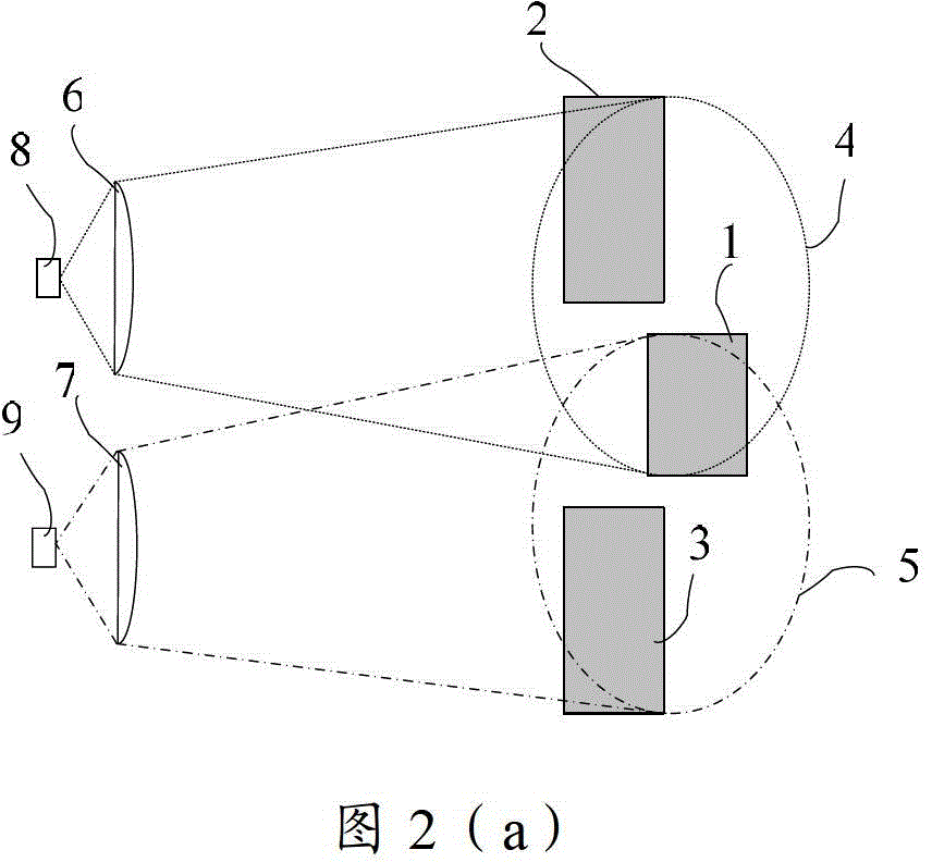
[0053] Wherein, the optical emitting unit is used to emit a single laser beam and can divide it into three laser beams. In this embodiment, the projection areas of the three laser beams are arranged in sequence; the optical receiving unit is used to receive the three laser beams. The target return light signal reflected by the projection area of the laser, and the received target return light signal is converted into a corresponding electrical signal; the processing unit is connected with the optical receiving unit for receiving the electrical signal and analyzing it to The azimuths of the targets within the projection areas of the three laser beams are obtained. Preferably, the projection areas of the three laser beams do not overlap in space, and the projection areas of the three laser beams are distributed in a zigz...
Embodiment 2
[0101] The difference between this embodiment and embodiment 1 is:
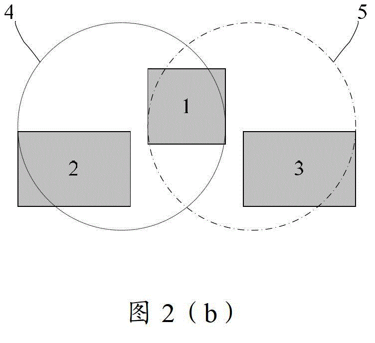
[0102] In the optical receiving unit of the radar sensor, the field of view area 4 of the first condensing lens covers the projection area 1 of the first laser and the projection area 2 of the second laser, and the field of view 5 of the second condensing lens covers the first The projection area 1 of the laser light and the projection area 3 of the third laser light are all covered. That is, the field of view area of each condensing lens can completely cover the projection areas of two adjacent laser beams among the three laser beams.
[0103] Other methods, structures, and functions in this embodiment are the same as those in Embodiment 1, and will not be repeated here.
PUM
 Abstract
Description
Claims
Application Information
 - Generate Ideas
- Intellectual Property
- Life Sciences
- Materials
- Tech Scout
- Unparalleled Data Quality
- Higher Quality Content
- 60% Fewer Hallucinations
Browse by: Latest US Patents, China's latest patents, Technical Efficacy Thesaurus, Application Domain, Technology Topic, Popular Technical Reports.
© 2025 PatSnap. All rights reserved.Legal|Privacy policy|Modern Slavery Act Transparency Statement|Sitemap|About US| Contact US: help@patsnap.com