
Power supply control circuit for relay driving module

A technology of power supply control circuit and drive module, which is applied in the direction of relays, circuits, electrical components, etc., can solve problems such as complex equipment environment, influence, and misoperation of external actuators, and achieve the effect of improving redundancy

Inactive Publication Date: 2012-10-24
SUZHOU IND PARK HESHUN ELECTRIC CO LTD
View PDF6 Cites 10 Cited by
  • Summary
  • Abstract
  • Description
  • Claims
  • Application Information

AI Technical Summary

Problems solved by technology

In practical applications, the following problems are often encountered: (1) The initialization time of tens of milliseconds is required for the device to be powered on, during which the state of the IO signal is uncertain; (2) The moment the device is powered off, due to the The existence of the processor, often the processor has lost power and stops controlling, and the peripheral IO is still in an unstable working state; (3) The environment in which the device is located is complex, and the control signal is easily affected by external electromagnetic interference
In the above three situations, IO is often in an uncontrolled or random state, or accompanied by glitches and pulses, which will lead to misoperation of output relays and misoperation of external actuators

Method used


Image

  • Power supply control circuit for relay driving module
  • Power supply control circuit for relay driving module
  • Power supply control circuit for relay driving module

Examples


Embodiment

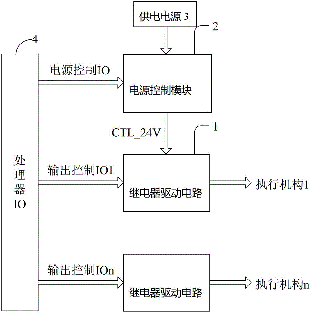
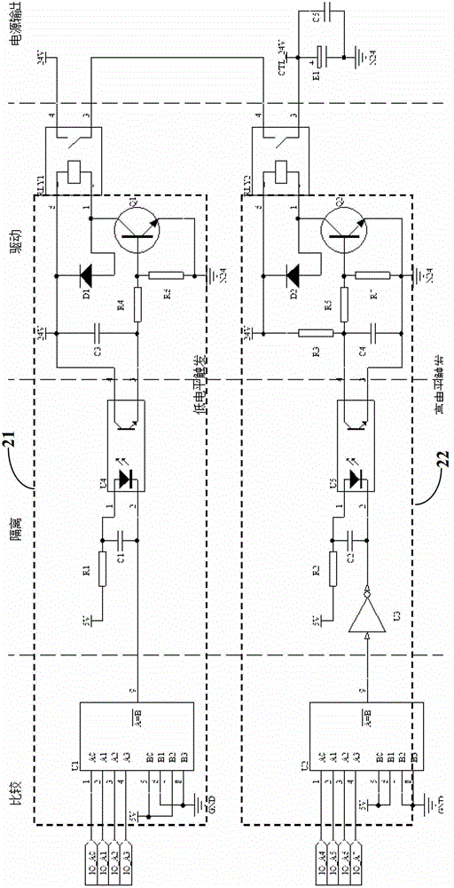
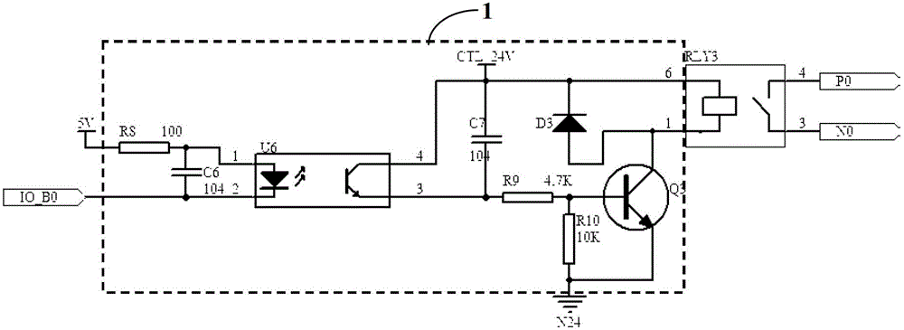
[0018] Embodiment: A power control circuit for a relay drive module, the relay drive module includes a relay drive module 1 connected to a first relay RLY3 for controlling the first relay RLY3; further comprising:

[0019] The processor 4 outputs a power control signal for controlling the power supply of the relay drive circuit and a relay control signal for controlling the on and off of the coil of the first relay RLY3;

[0020] A power control module 2 is provided between the controlled power supply node CTL_24V of the first relay RLY3 and the processor 4, and the power control module 2 is composed of a low-level trigger unit 21 and an output terminal of the low-level trigger unit 21. The second relay RLY1 is composed; one end of the second relay RLY1 normally open contact is connected to the 24V power supply for supplying power to the relay drive circuit 1, and the other end of the second relay RLY1 normally open contact is connected to the first The controlled power supply node...


PUM


Abstract

The invention relates to a power supply control circuit for a relay driving module, which comprises a processor; the processor outputs a power supply control signal used for controlling power supply of a relay driving circuit, and a relay control signal used for controlling on and off of a first relay coil; a power supply control module is arranged between a first relay controlled power supply node and the processor; the power supply control module consists of a low level trigger unit and a second relay connected with an output end of the low level trigger unit; one end of an output circuit of the second relay is connected with a power supply used for supplying power for the relay driving circuit, and the other end of the output circuit of the second relay is connected with the controlled power supply node which is arranged in a first relay and used for supplying power for the relay driving circuit; and the processor is set with default codes. The power supply control circuit effectively prevents equipment from being powered on or off and the malfunction of a relay caused by the external disturbance.

Description

Technical field [0001] The invention relates to a power control circuit for a relay drive module, belonging to the field of relay control. Background technique [0002] The relay is a very common device in the control system, used to realize the control of a variety of actuators, and is simple and reliable to use. In the prior art, the common relay drive circuit is one-to-one control, that is, one IO signal corresponds to the control of one output relay. The following problems are often encountered in practical applications: (1) It takes about tens of milliseconds to initialize the device when it is powered on, during which the state of the IO signal is uncertain; (2) The moment the device is powered off, due to the energy storage components in the circuit Existence, often the processor has lost power to stop control, and the peripheral IO is still in an unstable working state; (3) The environment of the device is complex, and the control signal is easily affected by external el...

Claims


Application Information

Patent Timeline
IPC IPC(8): H01H47/00
Inventor 费远鹏刘辉陈祥书吴祥兴
Owner SUZHOU IND PARK HESHUN ELECTRIC CO LTD
Learn More