

Inverter used for detecting solar cell panel and electric network side insulation resistor and detection method
A technology of solar panels and insulation resistance, which is applied in the direction of measuring electrical variables, measuring electricity, converting irreversible DC power input into AC power output, etc. problems such as resistance conditions, to achieve the effect of simplifying the detection circuit
Patent Information
- Authority / Receiving Office
- CN · China
- Patent Type
- Applications(China)
- Current Assignee / Owner
- Publication Date
- 2012-10-24
Smart Images
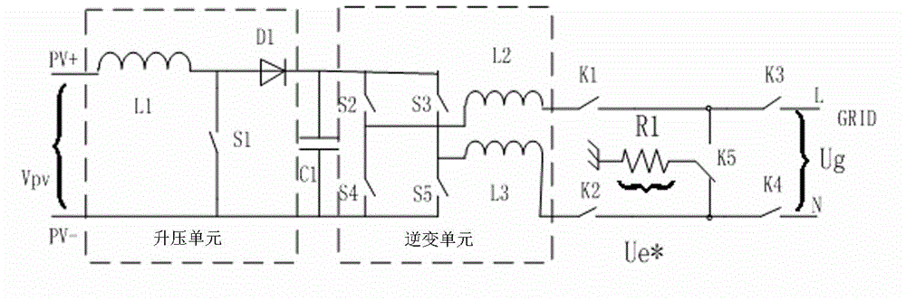
Figure 1 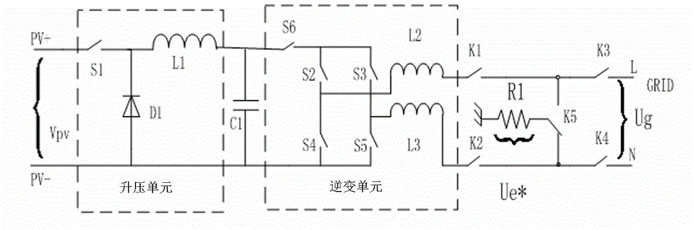
Figure 2 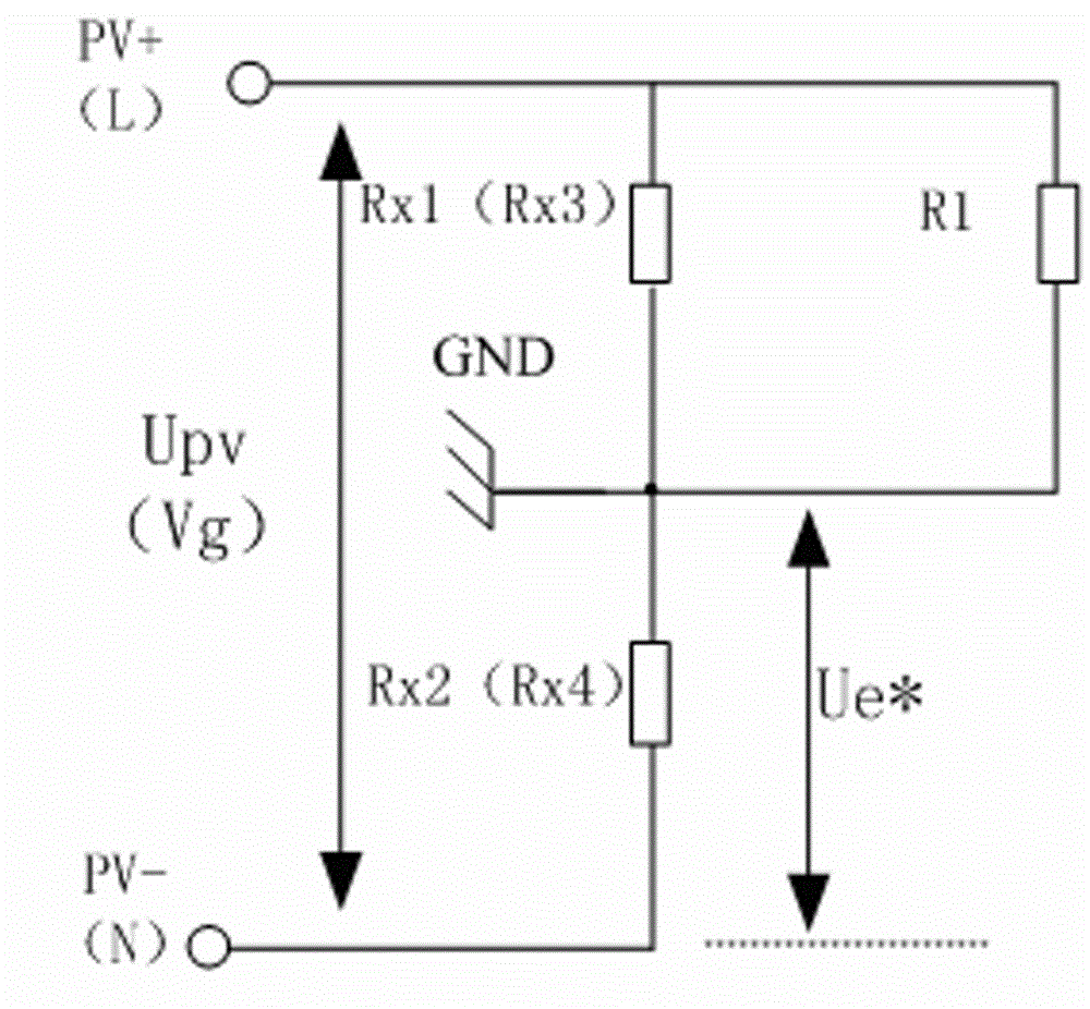
Figure 3
Abstract
Description
technical field
[0001] The invention relates to an inverter and a detection method for detecting the insulation resistance of a solar panel and a grid side. Background technique
[0002] In the photovoltaic grid-connected standards of many countries, there are regulations on the insulation resistance of non-isolated photovoltaic grid-connected inverters, which require that the insulation resistance between the positive and negative electrodes of the solar panel connected to the inverter is not less than the specified Therefore, it is very necessary to add the detection of insulation resistance to the non-isolated grid-connected inverter. At present, most of the detection of insulation resistance is by adding a simple circuit and then sampling related variables. , and then calculate the value of the insulation resistance through a digital processor.
[0003] At present, the practice of most inverters is to detect the insulation resistance value of the positive pole (negativ...
Examples
Embodiment 1
[0031] Example 1: see figure 1 , the present invention includes a boost unit, an inverter unit, the boost unit is connected in series with the inverter unit, the boost unit includes L1, S1 and D1, PV+ is first connected to one end of the inductor L1, the other end of L1 is connected to one end of D1, and D1 is followed by a capacitor C1 is used as an energy buffer unit. A switch S1 is connected between L1 and D1. The other end of S1 is connected to PV-. When S1 is turned on, energy is stored through inductor L1. When S1 is turned off, the energy of inductor L1 is transferred to C1 through D1. , to achieve the purpose of energy transmission. The inverter unit includes C1, S2, S3, S4, S5, L2 and L3, the switch S2, switch S4, switch S3, and switch S5 are connected in series at both ends of the capacitor, and the inductors L2 and L3 are respectively connected to the terminals of S2, S4, S3 and S5. At the middle point, the DC voltage on C1 is converted into AC voltage through the ...
Embodiment 2
[0033] Example 2, see figure 2, the step-up unit, the inverter unit can also have another form, the step-up unit is composed of S1, D1, L1, PV+ is directly connected to the switch S1, the other end connected to S1 is connected in series with inductor L1, and indirect diodes D1, D1 between S1 and L1 The other end is directly connected to PV- and the negative end of C1, and the inductor L1 is connected to the positive end of capacitor C1. The inverter unit is composed of S2, S3, S4, S5, and S6. S6 is connected in series between the bridge arms composed of C1 and S2, S3, S4, and S5. Switches S2, S4, S3, and S5 are connected in series with the capacitor C1 is connected in parallel at both ends, and inductors L2 and L3 are respectively connected to the midpoints of S2, S4, S3, and S5. Through the high-frequency switches of S2, S3, S4, and S5, the DC voltage on C1 is converted into AC voltage to realize energy output. . When S1, S2, S6, K1 are connected and K5 has a trigger signa...