Through physical separation-type Z-source inverter with high booster multiple

A technology with high boost multiple and physical separation, applied in output power conversion devices, AC power input conversion to DC power output, electrical components, etc. Problems such as limited multiples

Inactive Publication Date: 2012-10-24
HARBIN INST OF TECH AT WEIHAI
View PDF2 Cites 5 Cited by
  • Summary
  • Abstract
  • Description
  • Claims
  • Application Information

AI Technical Summary

Problems solved by technology

However, the original Z-source inverter has the following defects: 1. The actual insertable straight-through vector cannot be more than the zero vector in one switching cycle, resulting in a very limited actual achievable boost multiple
2. There is an interdependent relationship between the boost factor and the inverter factor, and the two ebb and flow. The red text is changed to: cannot be increased at the same time, which reduces the flexibility of the control strategy
[0003] Specifically, the original Z-source inverter has the following defects: The boost of t

Method used


Image

  • Through physical separation-type Z-source inverter with high booster multiple
  • Through physical separation-type Z-source inverter with high booster multiple
  • Through physical separation-type Z-source inverter with high booster multiple

Examples


Embodiment Construction

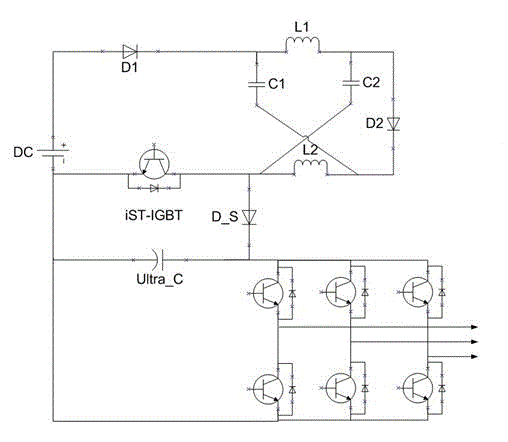
[0014] Such as figure 2 The straight-through physically separated Z-source inverter with a high boost multiple shown includes a DC voltage source DC, a first blocking diode D1 and a second blocking diode D2, a Z-source impedance network, and a three-phase inverter bridge, The Z source impedance network is composed of the first inductance L1, the second inductance L2, the first capacitor C1, and the second capacitor C2 to form an X-shaped structure. The present invention is characterized in that it also includes a full-control switching device iST-IGBT, a large capacitor ultra_C and a power diode. D_S; the anode of the direct current power supply DC is connected to the anode of the first blocking diode D1, the cathode of the first blocking diode D1 is connected to one end of the first inductor L1 in the Z source impedance network and the positive electrode of the first capacitor C1, and the second resistor The cathode of the off diode D2 is connected to the other end of the fi...


PUM


Abstract

The invention relates to a through physical separation-type Z-source inverter with high booster multiple, which relates to the field of Z-source inverters, and comprises a direct current voltage source, a first blocking diode, a second blocking diode, a Z-source impedance network and a three-phase inverter bridge; and the Z-source impedance network comprises a first inductor, a second inductor, a first capacitor and a second capacitor which form an X-shaped structure. The inverter is characterized by also comprising a full-control switch device, a large capacitor and a power diode; the negative pole of the second capacitor and the collector of the full-control switch device are parallelly connected to the anode of the power diode; the emitter of the full-control switch device is connected with the negative pole of a direct current power supply; the cathode of the power diode is connected with the positive input end of the three-phase inverter bridge; the large capacitor is parallelly connected with the three-phase inverter bridge; and the positive pole and the negative pole of the capacitors are respectively connected with the positive input end and the negative input end of the three-phase inverter bridge correspondingly. According to the through physical separation-type Z-source inverter with high booster multiple, no coupling relationship exists between a booster factor and an inverter factor, the through duty ratio is independently controlled, and the booster multiple which can be realized is high.

Description

technical field [0001] The invention relates to a Z-source inverter, which belongs to a power electronic conversion device. Specifically, it is a straight-through physically separated Z-source inverter with a high boost multiple and no coupling relationship between a boost factor and an inverter factor. Background technique [0002] Literature (F. Z. Peng, Z-source inverter, IEEE Trans. Ind. Appl., 2003, 39(2): 504- 510) proposed the original Z-source inverter, its structure is as attached figure 1 As shown, by adding an X-shaped impedance network between the DC power supply and the inverter bridge, the performance of the inverter is improved. Compared with the traditional voltage source and current source inverters, it has the following excellent characteristics: (1) It has the ability of step-up and step-down at the same time, and the multiple of step-up and step-down is determined by the step-up factor and the inverter factor; (2) In the SVPWM control algorithm, it is all...

Claims


Application Information

Patent Timeline
IPC IPC(8): H02M7/521
Inventor 王新生张华强朱子文曹煊
Owner HARBIN INST OF TECH AT WEIHAI
Why Eureka
Try Eureka