

X-ray ct apparatus
An X-ray, central position technology, applied in the direction of diaphragm for radiation diagnosis, radiation/particle processing, instruments for radiation diagnosis, etc., can solve the problem of high price
- Summary
- Abstract
- Description
- Claims
- Application Information
AI Technical Summary
Problems solved by technology
Method used
Image

Examples
no. 1 approach )
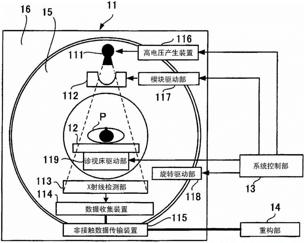
[0021] figure 1 The X-ray CT apparatus in the first embodiment is shown. The X-ray CT apparatus of this embodiment has: a gantry (gantry) 11 for scanning the subject P (patient) with X-rays; a bed 12 for moving the subject P into the gantry 11; a system The control unit 13 controls the entire X-ray CT apparatus; and the reconstruction unit 14 as a computer processes projection data obtained from the gantry 11 and reconstructs it into a medical image.
[0022] The gantry 11 is composed of a rotating part 15 that rotates around a subject P (patient) and a fixed part 16 other than that. The rotating part 15 has: an X-ray tube 111, which generates X-rays; a wedge 112, which adjusts the radiation distribution of the X-rays generated from the X-ray tube 111 in the direction of the fan angle; an X-ray detector 113, which detects the transmitted X-rays. X-ray of body P (patient); data acquisition device (DAS: Data Acquisition System) 114, which converts the detection data of X-ray d...
no. 2 approach )
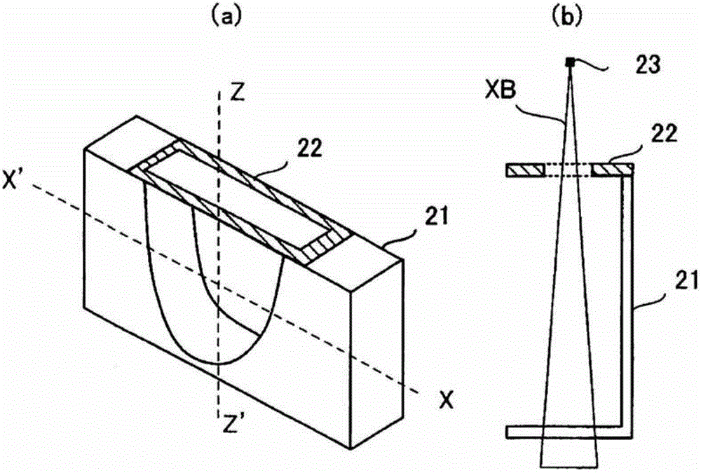
[0044] Figure 6 A modified example of the wedge is shown. Figure 6 (a) shows a perspective view, Figure 6 (b) is a cross-sectional view of a Z-Z' axis indicated by a dotted line as viewed along XX'.
[0045] In the first embodiment, the X-ray shield 22 is arranged on the upper portion of the wedge 21 (on the side of the X-ray tube 111 ), but in this embodiment, the X-ray shield 62 is arranged on the side of the wedge 61 .
[0046] When disposing the X-ray shield 62 on the side surface of the wedge 61, the thickness t and the height h of the X-ray shield 62 are determined in consideration of the spread of the X-ray beam. The width w is set to be substantially the same as the width of the wedge 61 . In addition, in the first embodiment, in order not to change the shape of the opening of the wedge 21 , the X-ray shield 22 is additionally arranged on the X-ray tube 111 side of the wedge 21 . Therefore, although the mechanical size of the wedge 21 can be changed, in this emb...
no. 3 approach )
[0049] According to the specifications of the X-ray CT apparatus, there is a type in which the position information of the wedge is reset to return the wedge position to the original position in order to ensure the position accuracy of the wedge when the wedge is driven. In an X-ray CT device of this specification, the dynamic collimation action of this embodiment cannot be realized within the scan cycle time. Therefore, by comparing the X-ray shielding position located outside the reconstruction range and the wedge center position in the reconstruction range The movement action between is realized by adding a new position detection method.
[0050] use Figure 7 The wedge drive unit 117 of the X-ray CT apparatus according to this embodiment will be described.
[0051] Such as Figure 7 As shown, there are: a ladder-shaped pattern 71, which is arranged on the top or side of the wedge 112 for position detection; a position detection part 73, which detects the position of the ...
PUM
 Abstract
Description
Claims
Application Information