Casting continuous cleaning flow line and method thereof

An assembly line and casting technology, which is applied in the field of continuous casting cleaning line, can solve the problems of large workplace area, low production efficiency, high labor intensity of workers, etc., and achieve the effect of saving workplace area, reducing floor space, and saving manpower consumption.

Inactive Publication Date: 2012-10-31
CRRC QIQIHAR ROLLING CO LTD
View PDF6 Cites 9 Cited by
  • Summary
  • Abstract
  • Description
  • Claims
  • Application Information

AI Technical Summary

Problems solved by technology

The main disadvantages of manual cleaning: 1. Because the castings are laid flat on the fixed flute, the working area is large. It is necessary to cut the riser, gouging and cutting core iron for each casting one by one. The labor intensity of the workers is high and the production efficiency is

Method used


Image

  • Casting continuous cleaning flow line and method thereof
  • Casting continuous cleaning flow line and method thereof
  • Casting continuous cleaning flow line and method thereof

Examples


Embodiment 1

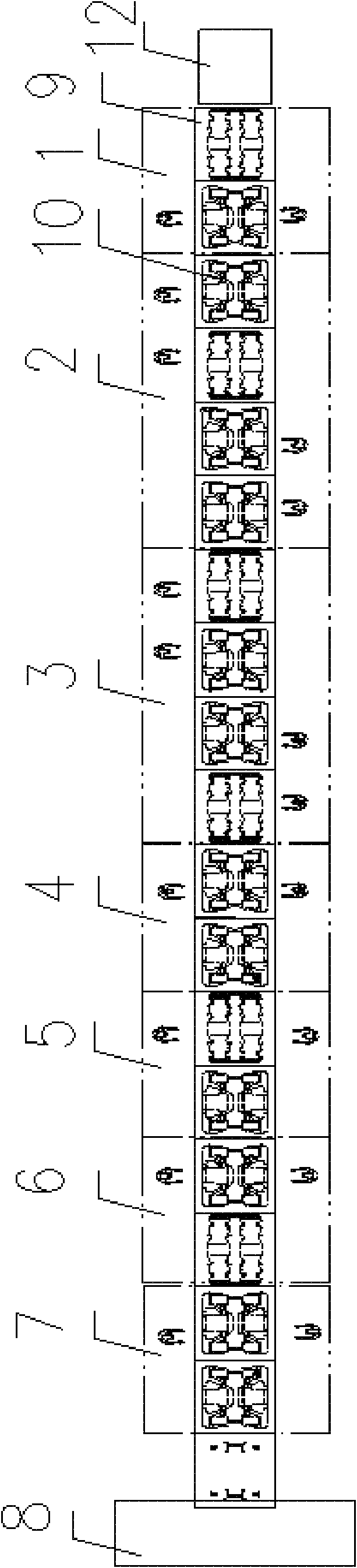
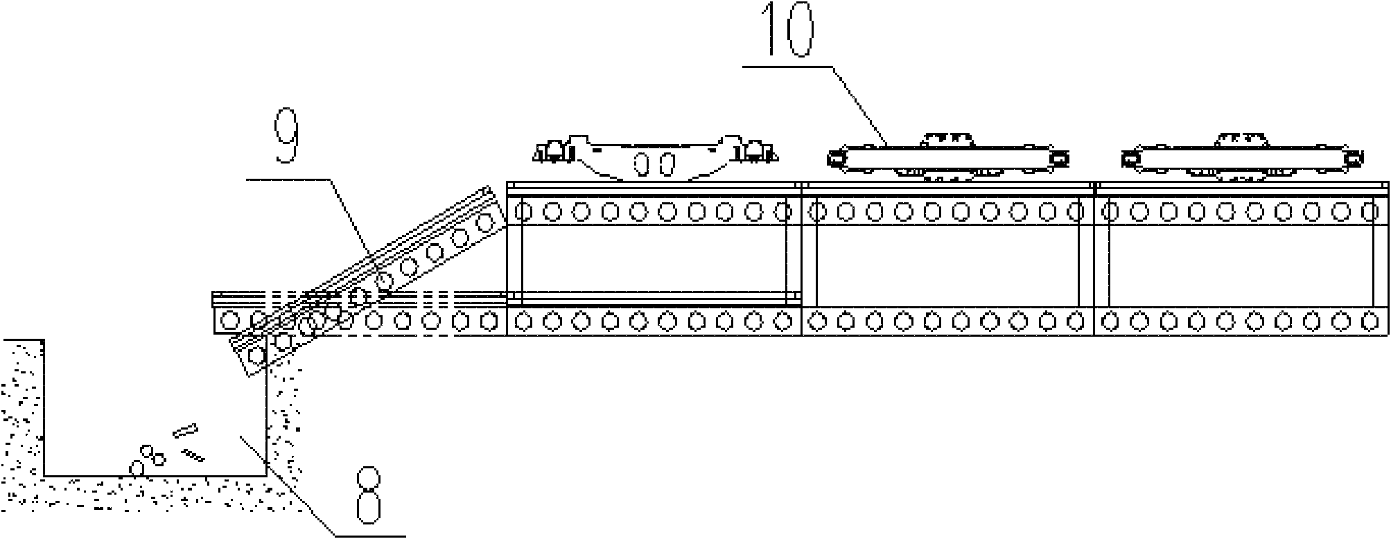
[0033] figure 1 It is a schematic diagram of the upper pipeline structure provided by the first embodiment of the present invention; figure 2 It is a schematic diagram of the bottom plate circulation provided by the first embodiment of the present invention.

[0034] The continuous casting cleaning line provided by this embodiment includes: a bottom plate 9, an upper line and a lower line. The upper line (also called the work roller) is figure 1 As shown, it includes the bottom plate feeding station, the upper part station 1, the primary cutting station 2, the primary gouging station 3, the turning station 4, and the secondary cutting station 5, which are sequentially set from the forward direction of the casting. There are nine stations for secondary gouging station 6, lowering station 7, floor automatic cleaning and return station. The casting residue collected by the automatic cleaning and return station of the bottom plate is poured into the residue collecting hopper 8. The ...

Embodiment 2

[0036] The continuous cleaning assembly line for castings provided by this embodiment includes: a bottom plate, an upper layer assembly line, and a lower layer assembly line. The bottom plate has a total of 18 pieces, and each two pieces of the bottom plate are placed side by side as a group, a total of 9 groups, and each station is composed of groups. The unit cleans up, with four castings on each group. The upper assembly line (also known as the work roller table) includes the bottom plate feeding station, the upper part station, the primary cutting station, the primary gouging station, the turning station, the secondary cutting station, and the secondary gouging station set in sequence. Automatic cleaning and return station of work station, loading station and bottom plate. The lower pipeline and the upper pipeline are connected end to end to form a closed operating loop.

[0037] The bottom plate circulates among the stations, and the bottom plate circulates between stations...

Embodiment 3

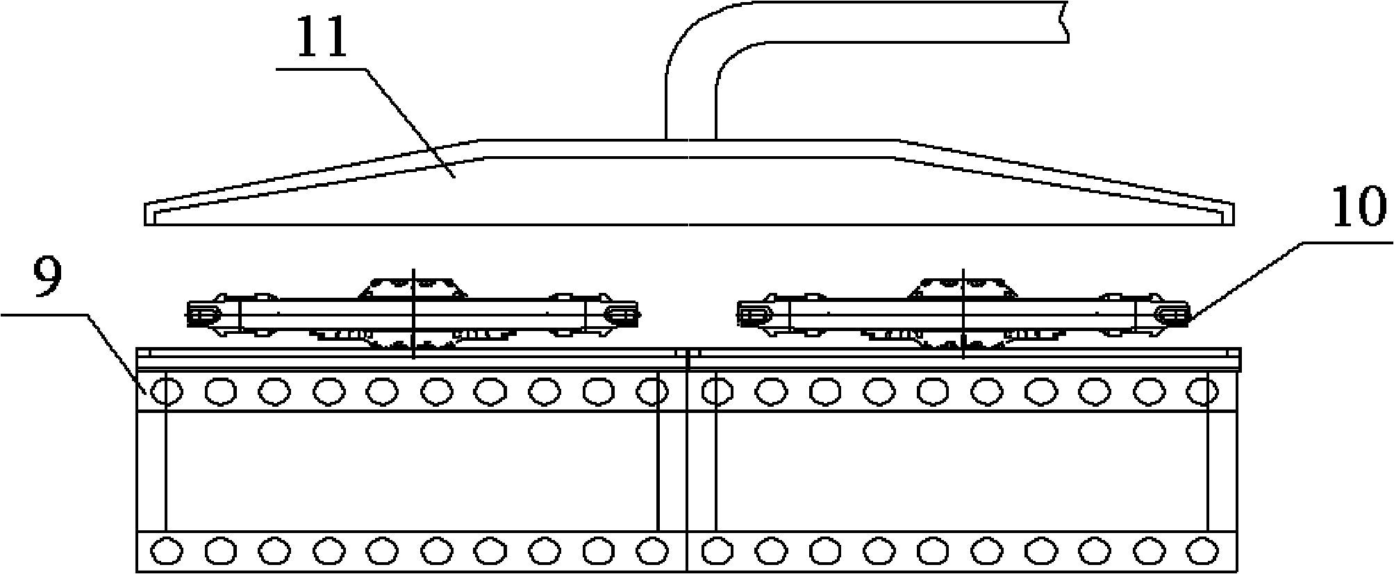
[0041] image 3 It is a schematic diagram of the structure of the top cover type dust collector of the third embodiment of the present invention.

[0042] The bottom plate, upper pipeline, and lower flow of the casting continuous cleaning line provided in this embodiment are the same as those in the second embodiment. The difference is that the casting continuous cleaning line provided in this embodiment has a single cutting station and a gouging station , The top of the operating point of the secondary cutting station and the secondary gouging station is provided with a top cover type dust collector 11, such as image 3 As shown, the casting 10 is placed on the bottom plate 9, and an inverted bucket-shaped top cover type dust collector 11 is arranged above the casting 10. The top cover type dust collector 11 can capture the smoke and dust generated by the heat floating and the smoke generated by the high-temperature arc combustion of the gouging carbon rod. The smoke and dust are...


PUM


Abstract

The invention discloses a casting continuous cleaning flow line and a method thereof. The casting continuous cleaning flow line comprises a bottom plate, an upper flow line and a lower flow line, wherein the upper flow line comprises a bottom plate feeding station, a workpiece loading station, a primary cutting station, a primary gouging station, an overturning station, a secondary cutting position, a secondary gouging station, a workpiece unloading station, a bottom plate automatic cleaning and returning station which are arranged in sequence; the bottom plate moves along the stations; the lower flow line is connected with the upper flow line end to end to form a closed operation loop; and through the lower flow line, the bottom plate can be transmitted from the bottom plate automatic cleaning and returning station to the bottom plate feeding station. The casting continuous cleaning flow line and the method thereof have the advantages that the various defects of the existing manual cleaning flow line are overcome, the mechanization and the pipelining of cleaning works of large quantities of steel castings are realized, cutting scraps are effectively and quickly collected, the whole equipment is safe and reliable, is long in service life and is convenient and simple to operate and maintain, and the work site area is saved.

Description

Technical field [0001] The invention relates to casting cleaning technology, in particular to a continuous casting cleaning line and method. Background technique [0002] my country has become a major country in foundry production. The cleaning process of castings is one of the most labor-intensive and worst-working processes in the foundry production process. While the molding and core-making technology is advancing and developing towards automation and high-tech, the cleaning technology of castings has been stagnant. At present, the main cleaning method adopted by the casting production plants is still manual cleaning, even for mass production castings. Manufacturers of steel parts (such as bolsters and side frames) have also failed to achieve mechanized or semi-mechanized production. [0003] The existing manual cleaning steps are to lay all the castings (one working day) on the fixed corrugation, and then manually cut the riser, gouging and core cutting of each casting one by ...

Claims


Application Information

Patent Timeline
IPC IPC(8): B22D31/00
Inventor 崔世海陈拥军王金朋景丹白文弟孙宝君张瀛褚福成凌云飞
Owner CRRC QIQIHAR ROLLING CO LTD
Why Eureka
Try Eureka