Long-shaft roller carrier

A roller frame and long shaft technology, applied in auxiliary devices, auxiliary welding equipment, welding/cutting auxiliary equipment, etc., can solve the problem of not being able to match short cylinder groups, and achieve the effect of simple structure and reasonable design

Inactive Publication Date: 2012-10-31
成都佳士科技有限公司
View PDF7 Cites 5 Cited by
  • Summary
  • Abstract
  • Description
  • Claims
  • Application Information

AI Technical Summary

Problems solved by technology

[0003] Aiming at the above-mentioned problems in the prior art that multiple sets of roller frames with traveling mechanisms are required for assembly and welding of ordinary roller frames and that short cylinders cannot be assembled, the present invention provides a multi-section cylinder that can be mounted on a roller frame The above pair of long-axis roller frames can completely solve the above problems

Method used


Image

  • Long-shaft roller carrier
  • Long-shaft roller carrier
  • Long-shaft roller carrier

Examples


Embodiment Construction

[0019] The present invention will be further described in detail below in conjunction with the accompanying drawings and specific embodiments.

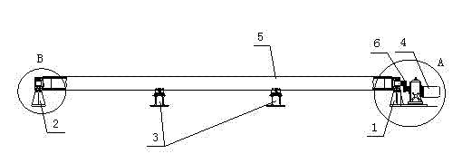
[0020] like Figure 1 to Figure 6 As shown, a long-axis roller stand includes an active support 1 and a driven support 2, two center frames 3 are arranged between the active support 1 and the driven support 2, and a pair of parallel rollers 5 are supported by the active support. Seat 1,

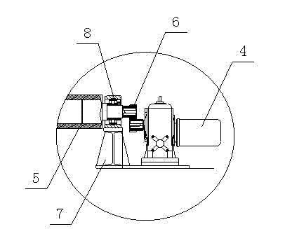
[0021] The driven support 2 is supported by the center frame 3, and one end of the roller shaft 5 located at the driving support 1 is connected to the output shaft of the worm gear reducer 4 through the gear set 6 to realize rotation.

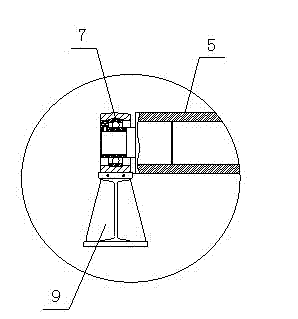
[0022] The active support 1 includes an active base 7 on which a bearing 8 is installed; the driven support 2 includes a driven base 9 on which a bearing 7 is installed.

[0023] Described center frame 3 comprises center frame base 10, and the roller 11 of supporting roller shaft 5 is set on the center frame base 10...


PUM


Abstract

The invention discloses a long-shaft roller carrier, which comprises a driving support and a driven support. A pair of rolling shafts is arranged in parallel between the driving support and the driven support. One end of each rolling shaft is connected with a speed reducer to rotate. The long-shaft roller carrier is simple in structure and rational in design; a plurality of barrels can be arranged on the roller carrier for pairing and welding; the lengths of the rolling shafts can be designed according to the lengths of the paired barrels; and the roller carrier is also applicable to the pairing and welding of short barrels.

Description

technical field [0001] The invention belongs to the technical field of welding equipment, and in particular relates to a long-axis roller frame used for barrel assembly and welding rotation displacement. Background technique [0002] At present, the common roller frame is used for cylinder assembly and welding. It needs to be supported by a group of roller frames for each section of the cylinder, and the roller frame is required to have a walking mechanism. Several sets of roller frames are required for several sections of the cylinder, and the equipment cost is relatively high. high. The master-slave roller frame is completely close to each other due to structural reasons, and there is a certain distance between the rollers. Therefore, it is not suitable for the assembly and welding of short cylinders. Contents of the invention [0003] Aiming at the above-mentioned problems in the prior art that multiple groups of roller frames with traveling mechanisms are required fo...

Claims


Application Information

Patent Timeline
Patent Type & Authority Applications(China)
IPC IPC(8): B23K37/053B25B11/00
Inventor 熊先伟杜云
Owner 成都佳士科技有限公司
Why Eureka
Try Eureka