Method for detecting states of control loops of electricity utilization collection terminals
A technology of electricity collection and state detection, which is applied to circuit breaker testing, electricity measurement, measurement devices, etc., can solve the problems of untimely detection, troublesome and difficult problem finding, etc., to achieve convenient operation, save labor, and improve economic effects and regulatory effect
- Summary
- Abstract
- Description
- Claims
- Application Information
AI Technical Summary
Problems solved by technology
Method used
Image

Examples
Embodiment 1
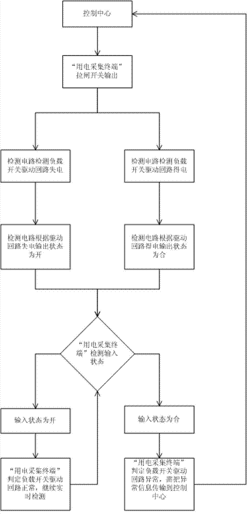
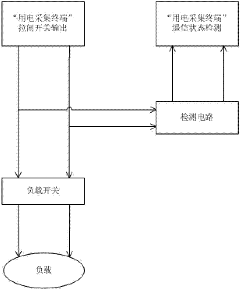
[0018] Such as figure 1 as shown, figure 2 the connections shown, and image 3 The connection structure of the industrial user first connects the load to the load switch, and when the load is running, the load switch that controls the load is regularly tested, and the load switch is connected to the remote signal detection switch;
[0019] The control center issues a switch output command to the power collection terminal, and the power collection terminal sends a switch control command. If the detection circuit detects that the drive circuit of the load switch is de-energized, the detection circuit will output power according to the de-energization of the drive circuit. The state is on, and the detection input state of the power collection terminal is on, then the detection input state of the power collection terminal determines that the load switch drive circuit is normal, and the signal instruction returns to the determination of the detection input state of the power coll...
Embodiment 2
[0022] According to the same steps as in Embodiment 1, the state of the load and the load switch and the remote signal detection switch are checked irregularly, and the same conclusion can be drawn. From the perspective of economy and rationality, this irregular inspection period is only to ensure the realization of the real-time monitoring of industrial users by the regulatory authorities.
Embodiment 3
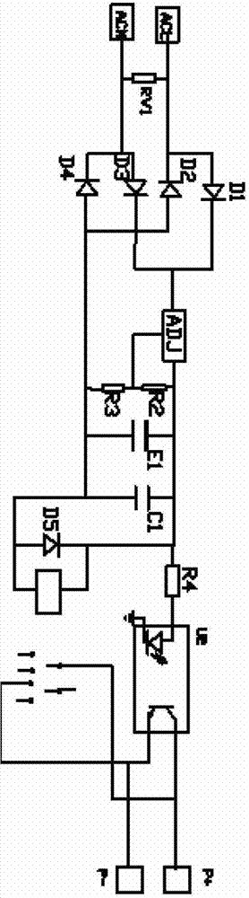
[0024] Such as figure 2 As shown, the remote signal detection switch is connected to the detection circuit, and then connected to the terminal switch and the load switch. The structure of the detection circuit is as follows image 3 The structure shown is composed of a power input terminal, a rectifier, a voltage regulator circuit, and a drive output circuit; wherein the power input terminal is connected to the rectifier device, the rectifier device is connected to the voltage regulator circuit, and the voltage regulator circuit is connected to the drive output circuit; in this implementation In the example, the driving current of the driving output circuit is greater than 4mA, the driving output circuit adopts a relay output circuit, the contact is normally open, and the fracture is closed when there is voltage, the relay adopts a micropower signal relay, and the rectifying device is a bridge rectifying device; To achieve the effect of the detection circuit, the inlet of the...
PUM
 Abstract
Description
Claims
Application Information
PatSnap Eureka turns technology decisions into work you can execute. Powered by our Innovation Knowledge Graph, it runs expert workflows across engineering, life sciences, materials and intellectual property. Get your review-ready output in minutes.


