Electromagnetic wire drying device

A technology of electromagnetic wire and center position, which is applied in the manufacture of circuits, electrical components, cables/conductors, etc. It can solve the problems of unreasonable structure, too large diameter of air outlet, and inability to achieve drying effect, and achieve reasonable structure and good drying effect. effect of effect

Active Publication Date: 2014-04-16
NEWONDER SPECIAL ELECTRIC
View PDF8 Cites 0 Cited by
  • Summary
  • Abstract
  • Description
  • Claims
  • Application Information

AI Technical Summary

Problems solved by technology

[0004] The purpose of the present invention is to solve the technical problems of unreasonable structure of the copper wire (magnet wire) blow-drying device in the prior art, too large diameter of the tuyere, and failure to increase the wind speed well, so that a good blow-drying effect cannot be achieved

Method used


Image

  • Electromagnetic wire drying device
  • Electromagnetic wire drying device
  • Electromagnetic wire drying device

Examples


Embodiment 2

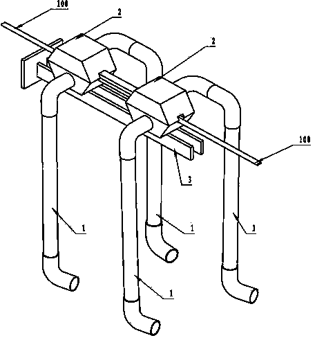
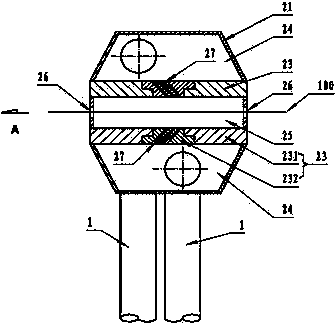
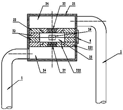
[0027] Embodiment two, see Figure 7 , the figure shows another blowing mechanism 2 of the electromagnetic wire drying device of the present invention. The difference from the blowing mechanism 2 in the previous embodiment is that the housing 21 is cylindrical and integral. The baffle 23 arranged in the housing 21 is in the shape of a cylindrical sleeve, the rear end of the baffle 23 has a locking ring 233 with a diameter larger than the front end and threaded surface, and the rear end of the housing 21 has a diameter smaller than the middle The threaded inner hole 211 whose position is matched with the locking ring 233 of the partition 23, the partition 23 is screwed with the threaded inner hole 211 at the rear end of the housing 21 through the locking ring 233 at the rear end, and the outer end of the locking sleeve 231 Lock nut 5 is arranged on and is used for locking both, prevents from loosening. The partition 23 divides the housing 21 into an outer air inlet chamber 24 ...


PUM


Abstract

The invention discloses an electromagnetic wire drying device which comprises a fan, an air inlet pipe, a blowing mechanism and a support. The electromagnetic wire drying device is characterized in that the blowing mechanism comprises a shell, a partition is arranged in the shell, the shell is divided into an air outlet cavity positioned at the center and an air inlet cavity positioned outside the center by the partition, the air inlet pipe is communicated with the air inlet cavity, the front center and the rear center of the air outlet cavity are respectively provided with a through hole, electromagnetic wires pass through the through holes, at least one slit-shaped air hole is arranged on the partition or between the partition and the shell, the air holes are opposite to the movement direction of the electromagnetic wires, and an acute angle is formed between each air hole and the corresponding electromagnetic wire. The electromagnetic wire drying device solves the problems that an existing copper wire drying device is provided with overlarge blow holes, air speed cannot be effectively increased, and further blowing effects are affected. The electromagnetic wire drying device has the advantages of reasonable structure and fine drying effects.

Description

technical field [0001] The invention discloses a drying device for electromagnetic wires, which belongs to auxiliary equipment for processing electromagnetic wires. Background technique [0002] In the production process of the magnet wire, the first step is to continuously extrude the copper material. After extrusion, the copper wire with a high temperature is introduced into the water tank for cooling. After cooling, the sticky water needs to be dried immediately. To avoid rusting of copper wire. In the existing production process, the drying of the copper wire is to use two air compressors to press the air in the air storage tank to dry the water, so there are the following problems: the noise of the air compressor is too large; and its power consumption The amount is large. Moreover, the air compressor is often shut down due to high temperature, which will cause waste of copper wires output from the copper wire production line if they are not dried in time, or need to ...

Claims


Application Information

Patent Timeline
Patent Type & Authority Patents(China)
IPC IPC(8): H01B13/30
Inventor 谭勇郑忠红王泉福
Owner NEWONDER SPECIAL ELECTRIC
Why Eureka
Try Eureka