Efficient heat dissipation electric power cabinet for electric power engineering

A technology of power engineering and power cabinets, applied in substation/power distribution device casing, electrical components, substation/switch layout details, etc., can solve problems such as heating of electrical components, limited number of fans, affecting normal operation of electrical components, etc., to achieve reduction The amount of dust and the effect of improving the heat dissipation effect

Active Publication Date: 2021-10-19
山东巨德电子设备有限责任公司
View PDF7 Cites 0 Cited by
  • Summary
  • Abstract
  • Description
  • Claims
  • Application Information

AI Technical Summary

Problems solved by technology

The high-power devices in the power cabinet will release a lot of heat when they work, and the heat must be dissipated in time. If the heat dissipation is not good, it will damage the service life and safety of the power devices.
The current power cabinet adopts fan cooling method to collectively dissipate heat and cool down all the electrical components in the power cabinet. However, due to the limited number of fans, only the electrical components near the fan have a better heat dissipation effect, and the electrical components far away from the fan have better heat dissipation. The effect is not good, resulting in uneven heat dissipation inside the power cabinet, which will affect the normal operation of electrical components over time, and in the process of cooling through the wind, even if there is a dust-proof filter, the dust doped in the outside air will enter more or less In the power cabinet, most of the dust is adsorbed on the electrical components, causing the electrical components to heat up and seriously affecting the normal operation of the electrical components

Method used


Image

  • Efficient heat dissipation electric power cabinet for electric power engineering
  • Efficient heat dissipation electric power cabinet for electric power engineering
  • Efficient heat dissipation electric power cabinet for electric power engineering

Examples


Embodiment Construction

[0019] Below in conjunction with accompanying drawing and specific embodiment the present invention is described in further detail:

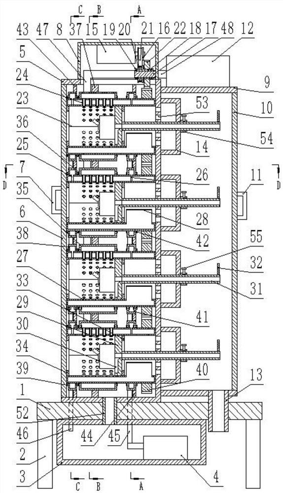
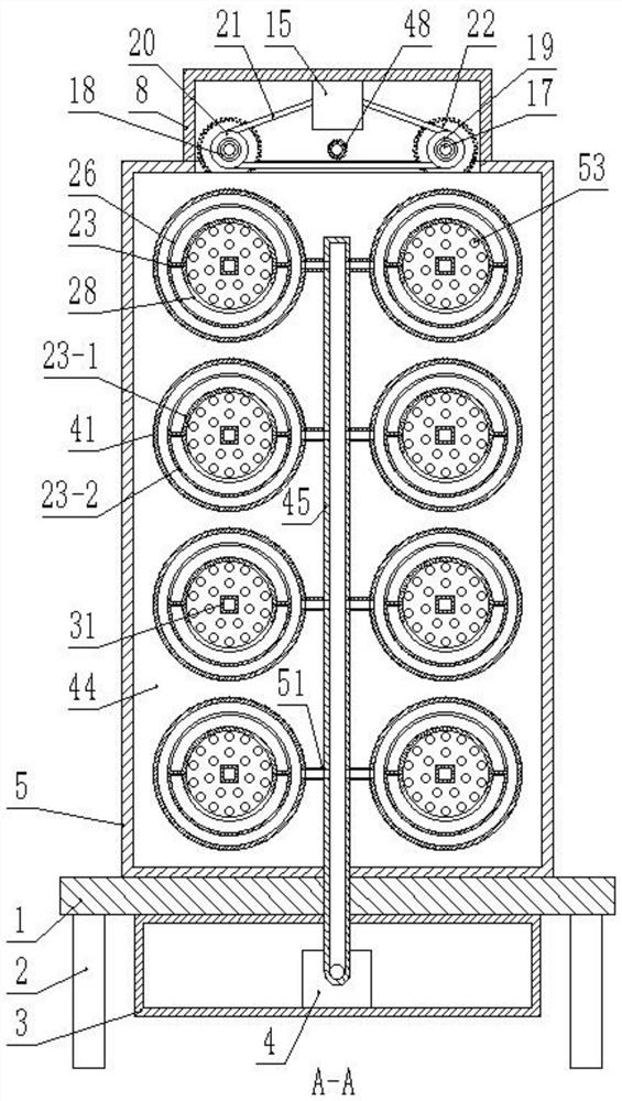
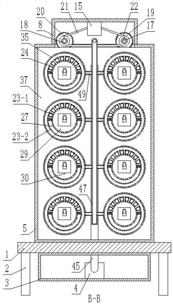
[0020] like figure 1 , figure 2 , image 3 , Figure 4 , Figure 5 , Image 6 , Figure 7 , Figure 8 As shown, a high-efficiency heat dissipation power cabinet for electric power engineering, including a base 1, is characterized in that; the four corners of the bottom of the base 1 are respectively fixed with outriggers 2, and the bottom of the base 1 is fixed with a water tank 3, and the water tank 3 is a A water inlet is opened on the side, a submersible pump 4 is fixedly installed on one side of the inner bottom of the water tank 3, a power cabinet body 5 is fixedly installed on the top surface of the base 1, and a box door 6 is hinged on one side of the power cabinet body 5, so A handle 7 is fixed on the side wall of the box door 6, a box body 9 is fixed on the other side of the power cabinet body 5, and a first box door 10 is hinge...


PUM


Abstract

The invention discloses an efficient heat dissipation electric power cabinet for electric power engineering. The cabinet comprises a base, and supporting legs are respectively fixed at four corners of the bottom surface of the base. According to the efficient heat dissipation electric power cabinet for the electric power engineering of the invention, each electric component is installed in an independent cylinder, so that the purpose of directly cooling each electric component in a one-to-one manner can be achieved, and the circulation process of cooling water in an inner cavity of a first arc-shaped plate can be achieved through a submersible pump, so that the cooling effect on air circulating in a ventilation pipe is effectively achieved; the air blown to the electrical components through the ventilation pipe is cooled, the heat dissipation effect of the electrical components is improved; slow rotation of each cylinder can be achieved at the same time through a motor, the air can be blown to each part of the electrical components in all directions, the heat dissipation effect of the electrical components is further improved; and in addition, due to the function of blowing air around the electric components in all directions, the amount of dust adsorbed on the electric components can be effectively reduced.

Description

technical field [0001] The invention relates to the field of electric power engineering, in particular to a high-efficiency heat dissipation power cabinet for electric power engineering. Background technique [0002] With the continuous development of intelligent power distribution, the requirements for power cabinets are getting higher and higher, such as PLC control cabinets, frequency conversion cabinets, etc., more and more precision components and power devices are used inside the power cabinets, and the more precise The more components have higher requirements on the use environment, such as the requirements on temperature, humidity, dust and other environments, especially the requirements on temperature. The high-power devices in the power cabinet will release a lot of heat when they work, and the heat must be dissipated in time. If the heat dissipation is not good, it will damage the service life and safety of the power devices. The current power cabinet adopts fan ...

Claims


Application Information

Patent Timeline
Patent Type & Authority Applications(China)
IPC IPC(8): H02B1/32H02B1/56H02B1/28
CPCH02B1/32H02B1/565H02B1/28
Inventor 韩飞
Owner 山东巨德电子设备有限责任公司
Why Eureka
Try Eureka