Inverted sound box structure

A speaker and shell technology, applied in the field of reverse speaker structure, can solve problems such as electrical conduction, and achieve the effect of low assembly cost and simple steps

Inactive Publication Date: 2012-10-31
SHENZHEN YUXINXIN ELECTRONICS
View PDF3 Cites 5 Cited by
  • Summary
  • Abstract
  • Description
  • Claims
  • Application Information

AI Technical Summary

Problems solved by technology

[0004] The technical problem to be solved by the present invention is to provide a reverse speaker structure to solve the problem of electrical conduction in the prior art, so as to facilitate assembly and save costs

Method used


Image

  • Inverted sound box structure
  • Inverted sound box structure
  • Inverted sound box structure

Examples


Embodiment Construction

[0039] Below in conjunction with accompanying drawing, structural principle and working principle of the present invention are specifically described:

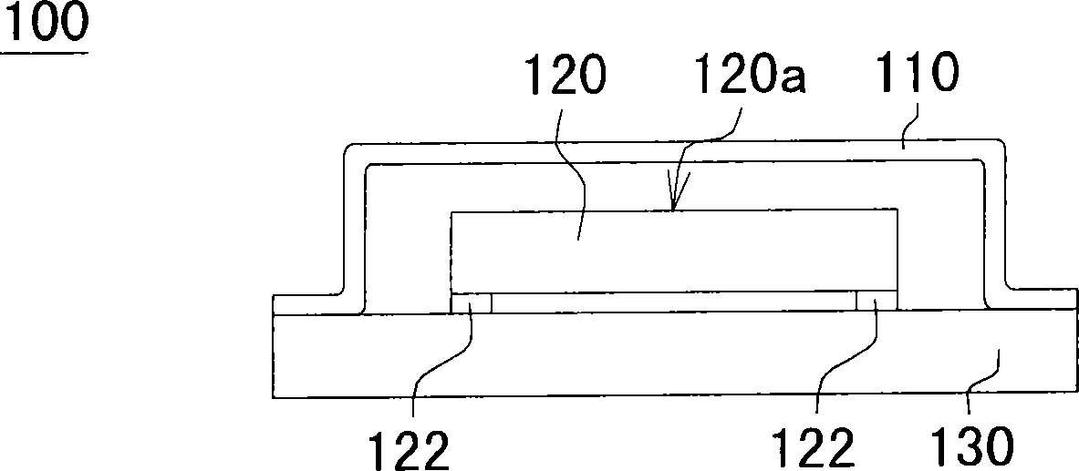
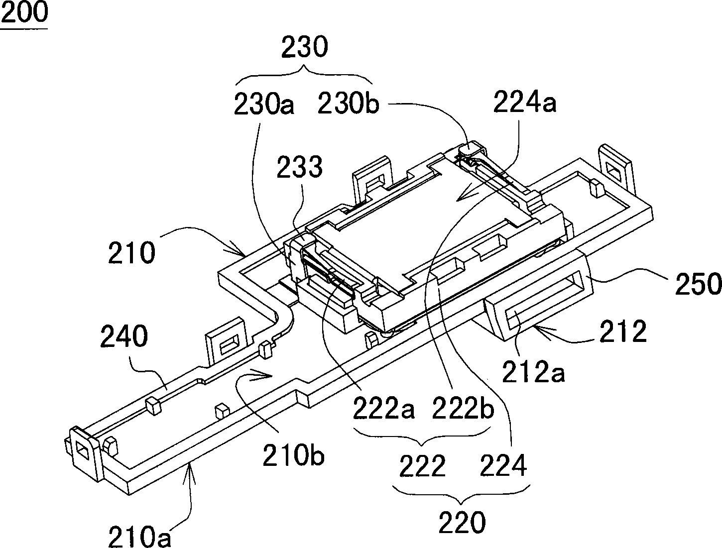
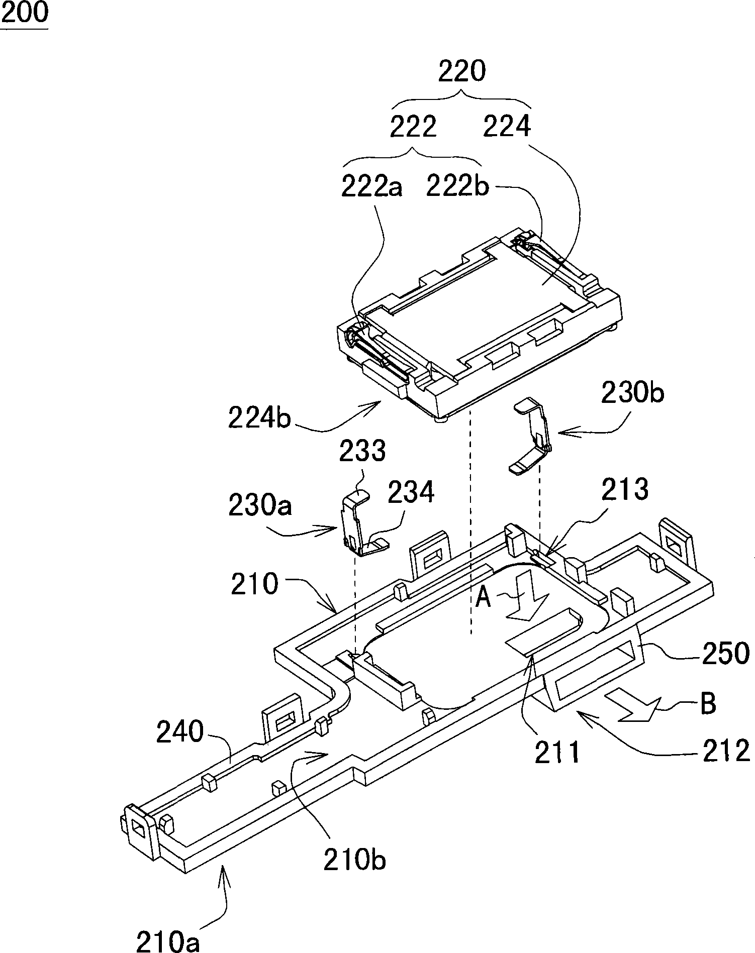
[0040] In the reverse speaker structure and fastener structure of this embodiment, the speaker unit and the speaker casing are placed on the circuit board upside down, so that the electrodes on the bottom surface face upward, and the sound output surface of the speaker faces downward. The reversed speaker unit can be fixed on one side of the speaker shell through a set of fasteners, and one end of each fastener is elastically fastened to the bottom surface of the speaker, and is electrically connected to the electrodes on the bottom surface. Therefore, in terms of assembly, the reverse speaker structure of this embodiment has the smallest volume to improve space utilization, and the position of the sound outlet of the front speaker can meet the design requirements, thereby achieving the appearance of the side sound outlet Desi...


PUM


Abstract

An inverted sound box structure comprises a sound box housing, a loudspeaker unit and a fastener, wherein a front sound box is arranged on a first side of the sound box housing; the loudspeaker unit comprises an electrode and a loudspeaker, and the electrode is located at the bottom of the loudspeaker; the sound-out surface of the loudspeaker is arranged on the sound box housing to give out a vibration sound into the front sound box; and the fastener is used for buckling the loudspeaker on a second side of the sound box housing, and one end of the fastener is elastically propped against the bottom of the loudspeaker and is electrically connected with the electrode.

Description

technical field [0001] The invention relates to a sound box structure, in particular to a reverse sound box structure. Background technique [0002] Please refer to figure 1 , which is a schematic cross-sectional view of a sound box structure in the prior art. In the prior art speaker structure 100 , the speaker unit 120 is generally in direct contact with the circuit board 130 through the electrodes 122 at the bottom or is connected to the circuit board 130 by welding wires. However, under the limitation of the height of the space, if the bottom of the speaker unit 120 is directly arranged on the circuit board 130, the sound output surface 120 must be arranged upwards and cannot be directly facing the sound output hole (not shown), resulting in the sound output of the speaker housing 110. The location of the sound hole will not meet the design requirements. In addition, if the bottom of the speaker unit 120 is arranged upward, there will be a problem that the electrodes ...

Claims


Application Information

Patent Timeline
Patent Type & Authority Applications(China)
IPC IPC(8): H04R1/02
Inventor 廖建中
Owner SHENZHEN YUXINXIN ELECTRONICS
Why Eureka
Try Eureka