Data center with low power usage effectiveness

A data center, data technology, applied in applications, home heating, home appliances, etc., can solve problems such as microprocessor errors and failures, chip cooling chips, etc., to reduce the total water volume

Active Publication Date: 2012-10-31
GOOGLE LLC
View PDF5 Cites 11 Cited by
  • Summary
  • Abstract
  • Description
  • Claims
  • Application Information

AI Technical Summary

Problems solved by technology

Heat removal can also be important because although a microprocessor may not be as sensitive to heat as a human being, an increase in heat can generally ca

Method used


Image

  • Data center with low power usage effectiveness
  • Data center with low power usage effectiveness
  • Data center with low power usage effectiveness

Examples


Embodiment Construction

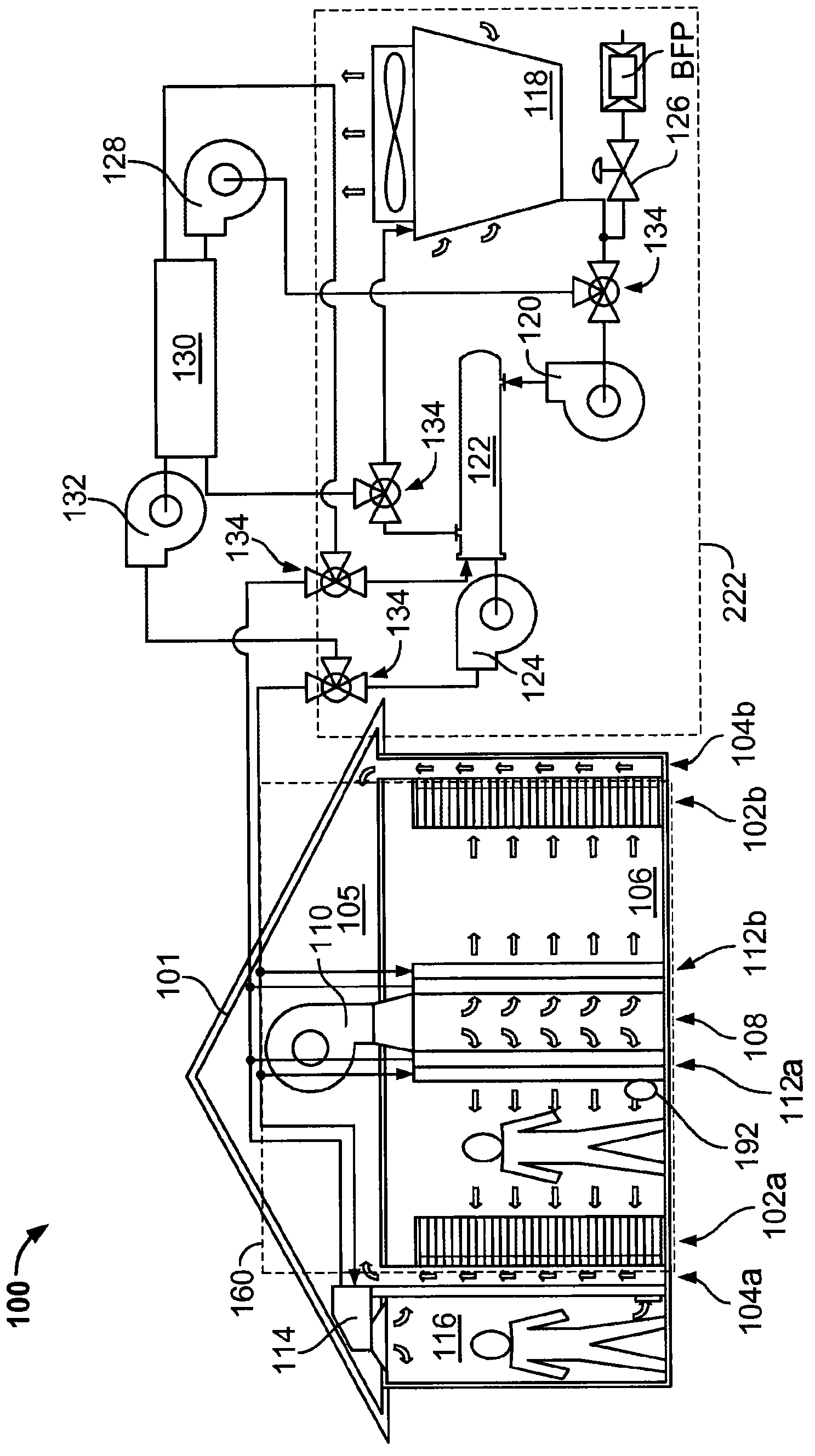
[0024] figure 1 is a schematic diagram illustrating a system 100 for cooling a computer data center 101 . System 100 generally includes an above-floor cooling unit 160 with a hot air handling unit (eg, including fan 110 and cooling coils 112a, 112b) for conveying air from the data center to cooling water. System 100 may also include modular cooling plant 222 . Modular cooling plant 222 may include a power and cooling unit ("PCU") with pumps 124, 120, valves 134, filters (not shown) and a heat exchanger 122 , the condenser water is delivered to cooling tower 118 in modular cooling plant 222 . The cooling towers 118 in the modular cooling plant 222 are cooling water towers, dry coolers (including only fan coil units), or hybrid towers (including both cooling water towers and dry coolers). Alternatively, a cold water source such as a lake or bay may be used instead of cooling tower 118 . The cooling towers 118 in the modular cooling plant 222 transfer accumulated heat to amb...


PUM


Abstract

A system for providing cooled air to electronic equipment includes a data center having electronic equipment in operation, a plurality of on- floor cooling units, and a cooling water source. The on-floor cooling units cool air warmed by the electronic equipment. The cooling water source is configured to supply cooling water that reduces a temperature of the on-floor cooling units. The power usage effectiveness ("PUE") of the system is less than 1.3, wherein the PUE is defined by energy used to operate the data center divided by energy used to run the electronic equipment.

Description

[0001] Cross References to Related Applications [0002] This application claims priority under 35 U.S.C. §119(3) to U.S. Application No. 12 / 611,061, filed November 2, 2009, the disclosure of which is incorporated herein by reference, and entitled DATA CENTER WITH LOW POWER USAGE EFFECTIVENESS . technical field [0003] This document relates to systems and methods for providing cooling to areas containing electronic equipment, such as computer server rooms and server racks in computer data centers. Background technique [0004] Computer users are often concerned with the speed (eg, megahertz and gigahertz) of a computer's microprocessor. Many people forget that this speed often comes with a cost - higher electrical power consumption. For a home PC or two, this extra power is negligible when compared to the cost of running many other appliances in the home. But in data center applications where thousands of microprocessors may be operating, electrical power requirements c...

Claims


Application Information

Patent Timeline
IPC IPC(8): F24F11/02F24F7/10F24F7/06
CPCF24F11/0001F24F2011/0006H05K7/20836H05K7/20745H05K7/2079H05K7/20827
Inventor A·B·卡尔森G·P·伊姆瓦尔T·R·科瓦尔斯基
Owner GOOGLE LLC
Why Eureka
Try Eureka