
Mini-cultivator speed-change mechanism

A technology of variable speed mechanism and micro-tiller, which is applied to agricultural machinery and implements, agricultural machinery, mechanical equipment, etc., can solve the problems of low reliability, slow driving speed, and inflexible speed changes, and achieves high reliability and simple structure. Effect

Inactive Publication Date: 2012-11-07
江伟
View PDF9 Cites 10 Cited by
  • Summary
  • Abstract
  • Description
  • Claims
  • Application Information

AI Technical Summary

Problems solved by technology

In the prior art, there are the following deficiencies: 1. Most of the existing micro-tillers have fewer shifting gears, and only need to set the gears for plowing. The speed change is not flexible enough, and it is impossible to better complete ditching, In addition, due to the lack of gears, the driving speed is relatively slow in places other than plowing fields, such as roads; 2. Even if a few micro tillage machines are equipped with multiple gears, these speed change mechanisms are usually equipped with multiple transmissions. shaft, which not only leads to a large and bulky transmission, but also a complex structure that leads to a low reliability of the transmission mechanism.

Method used


Image

  • Mini-cultivator speed-change mechanism
  • Mini-cultivator speed-change mechanism

Examples


Embodiment Construction

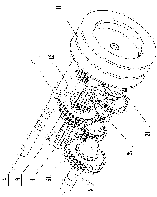
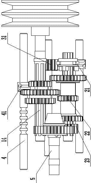
[0010] Such as figure 1 and 2 As shown, the present invention provides a speed change mechanism for a tiller, comprising a driving shaft 1, a driven shaft 2, a reverse gear shaft 3, a shift fork shaft 4 and an output shaft 5, and the driving shaft 1 is provided with a belt driven wheel 11 and The driving triple gear 12 that can move axially along the driving shaft 1, the driven shaft 2 is provided with a clutch gear 21 that can move along its axial direction, a driven triple gear 22 that is rotatably matched with it, and a driven gear fixed on the driven shaft. The drive shaft output gear 23, the reverse gear shaft 3 is provided with a reverse gear 31, the shift fork shaft 4 is provided with a shift fork 41, and the output shaft 5 is provided with a driving gear 51 which is constantly meshed with the driven shaft output gear 23 .

[0011] The axial center of the driving triple gear 12 is provided with tooth grooves, the surface of the driving shaft 1 is provided with bar tee...


PUM


Abstract

The invention relates to an agricultural mini-cultivator used for farming paddy fields and dry fields, in particular to a mini-cultivator speed-change mechanism. The mini-cultivator speed-change mechanism comprises a driving shaft, a driven shaft, a reverse gear shaft, a shift fork shaft and an output shaft, wherein the driving shaft is provided with a belt driven wheel and a driving triple gear capable of moving along the axial direction of the driving shaft, the driven shaft is provided with a clutch gear capable of moving along the axial direction of the driven shaft, a driven triple gear rotationally matched with the driven shaft and a driven shaft output gear fixed on the driven shaft; the reverse gear shaft is provided with a reverse gear; the shift fork shaft is provided with a shifting fork; the output shaft is provided with a driving gear engaged with the driven shaft output gear; the driving shift fork shaft is provided with a sliding chute matched with the shifting fork; the driving shift fork shaft is engaged with the driven shift fork shaft in a one-to-one correspondence way under the action of the shifting fork; and the side of the driven shaft shift fork shaft is provided with a slot capable of being connected with the clutch gear into a whole in a blocking way. The speed-change mechanism has the following characteristics of multiple gears, simple structure and high reliability.

Description

technical field [0001] The invention relates to an agricultural cultivating machine for cultivating paddy fields and dry land, in particular to a speed change mechanism of a micro tillage machine. Background technique [0002] In hilly areas and mountainous areas with large ground slopes, and in small paddy fields, large-scale agricultural machinery cannot exert its power, and more human or animal power is used, which is labor-intensive and low in production efficiency. In view of this present situation, agricultural tillage machine has occurred at present. In the prior art, there are the following deficiencies: 1. Most of the existing micro-tillers have fewer shifting gears, and only need to set the gears for plowing. The speed change is not flexible enough, and it is impossible to better complete ditching, In addition, due to the lack of gears, the driving speed is relatively slow in places other than plowing fields, such as roads; 2. Even if a few micro tillage machines ...

Claims


Application Information

Patent Timeline
Patent Type & Authority Applications(China)
IPC IPC(8): A01B71/06F16H37/02F16H3/093
Inventor 江伟
Owner 江伟
Learn More