
Mobile X-ray televisions

A mobile and TV technology, applied in medical science, equipment for radiological diagnosis, diagnosis, etc., can solve the problems of large scattering dose, inability to display, and inability to see the results immediately

Inactive Publication Date: 2012-11-07
THE KE SHI MEDICAL IMAGE TECHN RES INST
View PDF10 Cites 2 Cited by
  • Summary
  • Abstract
  • Description
  • Claims
  • Application Information

AI Technical Summary

Problems solved by technology

However, this kind of bedside machine has many disadvantages. First, it is not easy to accurately locate the lesion; second, the result cannot be seen immediately, and the X-ray film must be taken back to the darkroom to be washed before the disease can be seen; What's more, the scattering dose generated during filming is large, which has a great impact on the surroundings. In order to strengthen the protection of doctors, the technicians who are filming not only wear lead protective clothing, but sometimes they have to go outside the ward to escape.
Although there is also a kind of X-ray machine with TV currently available on the market (usually called "C-arm"), it is usually used to see through patients, and the results can be seen on the screen in time, but due to its The volume is too large to be used between the two beds in the ward, so it cannot be used in the ward at all

Method used


Image

  • Mobile X-ray televisions
  • Mobile X-ray televisions

Examples


Embodiment Construction

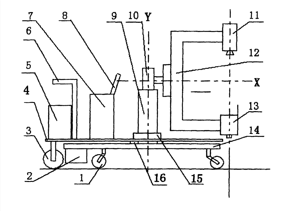
[0012] U-shaped arm - the assembly sequence of the whole machine is as follows:

[0013] 1. First weld the circular holding tube (9) and the load bar (14);

[0014] 2. Install the lower bearing (16), put on the bottom plate (4), and tighten the upper bearing (15);

[0015] 3. Then install the two rotary small wheels (1) under the load bar (14) and the two rear wheels (3) under the bottom plate (4);

[0016] 4. Install a small counterweight (2) on a section of the load bar;

[0017] 5. Insert the circular column (10);

[0018] 6. Install the chassis (7) and monitor (8); install the counterweight (5) on the bottom plate (4);

[0019] 8. Install the U-shaped square bar (12) on the circular column (10);

[0020] 9. Install the machine head (11) and imaging system (13) on the U-shaped square bar (12) respectively

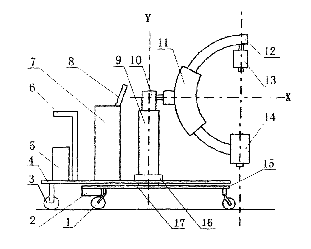
[0021] C-arm - the assembly sequence of the whole machine is as follows:

[0022] 1. First weld the circular holding tube (9) and the load bar (15);

[0023] 2. P...


PUM


Abstract

The invention discloses mobile X-ray televisions. Two involved X-ray machines which are used for X-raying patients beside hospital beds are a U-shaped arm mobile X-ray television and a C-arm mobile X-ray television, and can be directly pushed into wards to use. Referring to a representative drawing, the U-shaped arm mobile X-ray television is a U-shaped arm consisting of a machine head (11), an imaging system (13) and a U-shaped square bar (12). The complete machine of the mobile X-ray television can be directly pushed into the wards and conveniently placed between two hospital beds through a portable trolley; and the aim of x-raying can be fulfilled and the mobile X-ray television cannot be overturned only by rotating the U-shaped arm at an angle of + / -90 degrees during X-raying.

Description

technical field [0001] The patented mobile X-ray television of the present invention specifically relates to two kinds of radiation equipment suitable for pushing the X-ray machine into the ward and performing timely X-ray examination for seriously ill patients lying in bed. Background technique [0002] Radiology doctors often need to push the X-ray machine into the ward and take X-rays for the patient next to the bed if they encounter a patient who is too weak to walk or move. . This kind of X-ray machine is generally referred to as "bedside (X-ray) machine", (or "mobile X-ray machine"), especially for those seriously ill patients with orthopedic diseases. It is common for patients to take films. However, this kind of bedside machine has many disadvantages. First, it is not easy to accurately locate the lesion; second, the result cannot be seen immediately, and the X-ray film must be taken back to the darkroom to be washed before the disease can be seen; What's more, th...

Claims


Application Information

Patent Timeline
IPC IPC(8): A61B6/00
Inventor 吴佑之
Owner THE KE SHI MEDICAL IMAGE TECHN RES INST
Learn More