
Seal water system

A technology for sealing water and mechanical seals, which is applied in the sealing of engines, cleaning hollow objects, engine components, etc., can solve the problems of wasting water, expensive, polluting the environment, etc., and achieve the effect of reducing the burden on the environment

Inactive Publication Date: 2012-11-07
KRONES AG
View PDF7 Cites 3 Cited by
  • Summary
  • Abstract
  • Description
  • Claims
  • Application Information

AI Technical Summary

Problems solved by technology

Since this seal water system optionally employs a seal water throughput greater than or equal to 100 l / h and is optionally in permanent operation, this means that a large amount of water is wasted, especially in arid regions, which is disadvantageous, fact expensive and pollute the environment

Method used


Image

  • Seal water system
  • Seal water system
  • Seal water system

Examples


Embodiment Construction

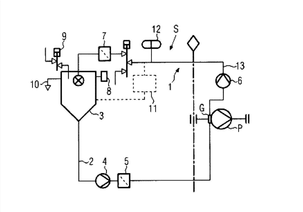
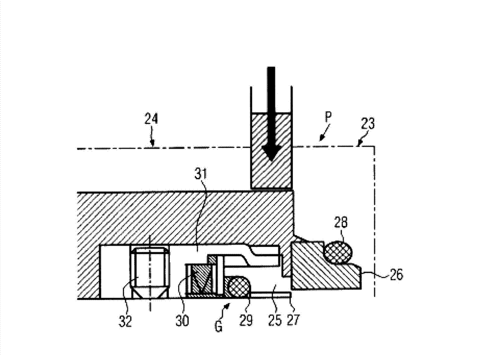
[0021] For example in image 3 Schematically shown in , since rotary mechanical seals G provide constant and good sealing performance, they are used, for example, in high-efficiency pumps. The rotary mechanical seal G will function best within a predetermined temperature range, as that maintains a certain sealing gap, however, this sealing gap will result in a certain leakage through the rotary mechanical seal. In pumps used, for example, in beverage transport technology or bottling technology, the transported food must not be subject to any contamination, for example due to leakage of rotary mechanical seals. On the one hand, also in order to adjust the specific operating temperature of the rotary mechanical seal, and on the other hand, in order to discharge contaminants or prevent contamination from mixing with the transported food, the sealing water is usually allowed to act on the rotary mechanical seal.

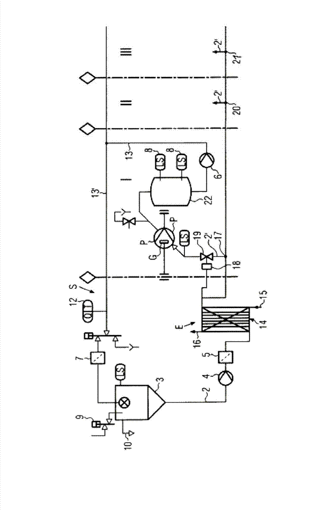
[0022] figure 1 Shown is a seal water system S for at least one r...


PUM


Abstract

A sealing water system for flushing at least one rotating mechanical seal(G) in at least one pump (P) includes a closed circuit. A supply pump is disposed in the closed circuit so as to act upon the rotating mechanical seal with sealing water. The closed circuit is configured to collect and recirculate the sealing water.

Description

technical field [0001] The invention relates to a sealing water system according to the preamble of patent claim 1 . Background technique [0002] In known seal water systems for flushing at least one rotating mechanical seal, for example in high-performance pumps in beverage processing or beverage bottling technology, possibly contaminated seal water is treated or drained. Since this seal water system optionally employs a seal water throughput greater than or equal to 100 l / h and is optionally in permanent operation, this means that a large amount of water is wasted, especially in arid regions, which is disadvantageous, fact expensive and pollute the environment. In the Federal Republic of Germany, seal water systems for rotary mechanical seals of high-performance pumps produce absolutely Among other things, the cost of water, where not only the prescribed cost but also the cost of wasted water must be considered. Contents of the invention [0003] It is an object of ...

Claims


Application Information

Patent Timeline
IPC IPC(8): B08B3/00
CPCB08B9/00F16J15/406Y10T137/85978
Inventor 迪尔克·洛伊茨
Owner KRONES AG
Learn More