
Manipulator

A manipulator, part of the technology, applied in the direction of manipulators, tubular objects, packaging, etc., can solve the problems of high labor intensity, low production efficiency, and many labors, and achieve the effect of high automation, high production efficiency and convenient operation

Inactive Publication Date: 2012-11-07
TIANJIN MINGTANG ENVIRONMENTAL PROTECTION TECH
View PDF0 Cites 6 Cited by
  • Summary
  • Abstract
  • Description
  • Claims
  • Application Information

AI Technical Summary

Problems solved by technology

[0002] In the existing technology, the welding rods are generally grasped manually in the packaging process of the welding rods. Due to the large output of welding rods, and the weight of a single package of welding rods is up to 5kg, the process of manually grasping the welding rods and packaging the welding rods needs to be compared. There is a lot of labor, and the labor intensity is high, the production efficiency is low, and it is out of touch with the production speed of the welding rod automatic production line

Method used


Image

  • Manipulator
  • Manipulator

Examples


Embodiment Construction

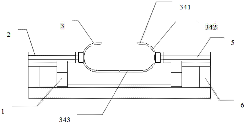
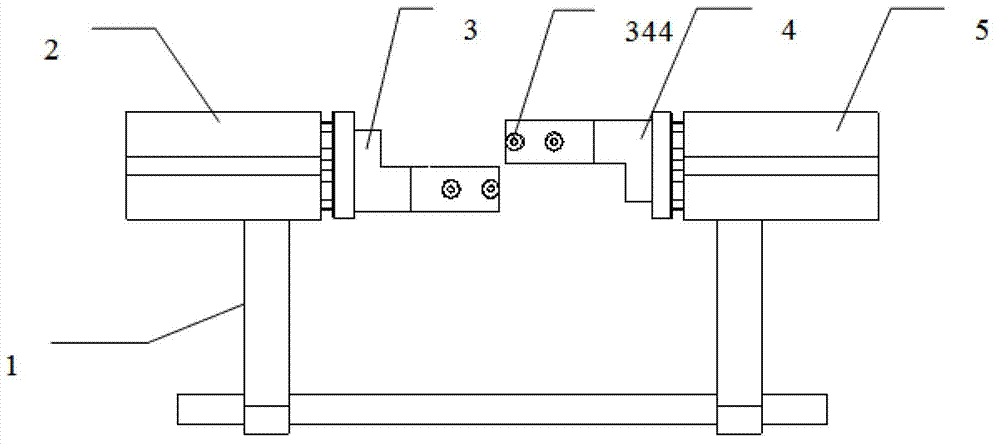
[0019] Such as figure 1 , 2 As shown, the present invention provides a kind of manipulator, comprises support bar 1, left draw in cylinder 2, right draw in cylinder 5, left manipulator 3, right manipulator 4, left manipulator 3 and right manipulator 4 are all formed by arc plate 342, lower nipper 343 and upper nipper 341, the lower nipper 343 and upper nipper 341 of the left and right manipulators are respectively connected with their respective arc-shaped plates 342, the lower nippers of the left manipulator 3 and the lower nippers of the right manipulator 4 are arranged alternately, the left The upper nipper of the manipulator 3 and the upper nipper of the right manipulator 4 are arranged alternately, the arc plate of the left manipulator 3 is fixed on the piston rod of the left retracting cylinder 2, and the arc plate of the right manipulator 4 is fixed on the piston of the right retracting cylinder 5 On the rod, the left retracting cylinder 2 and the right retracting cyli...


PUM


Abstract

The invention provides a manipulator which comprises supporting rods, a left converging air cylinder, a right converging air cylinder, a left manipulator body and a right manipulator body. Each of the left manipulator body and the right manipulator body is composed of an arc plate, a lower nipper plate and an upper nipper plate, the lower nipper plate and the upper nipper plate of the left manipulator or the right manipulator are respectively connected with the respective arc plate of the left manipulator or the right manipulator, the lower nipper plates of the left manipulator and the right manipulator are arranged in a staggered manner, the upper nipper plates of the left manipulator and the right manipulator are arranged in a staggered manner, the arc plates of the left manipulator and the right manipulator are respectively fixed on piston rods of the left converging air cylinder and the right converging air cylinder, and the left converging air cylinder and the right converging air cylinder are symmetrically arranged and fixed on the supporting rods. The manipulator has the advantages of simple structure, convenience in operation, high degree of automation, high working efficiency and the like, and packing of a welding rod clamped by the manipulator is more convenient.

Description

technical field [0001] The invention belongs to the field of manipulator equipment, and in particular relates to a manipulator used for gripping welding rods on a welding rod packaging production line. Background technique [0002] In the existing technology, the welding rods are generally grasped manually in the packaging process of the welding rods. Due to the large output of welding rods, and the weight of a single package of welding rods is up to 5kg, the process of manually grasping the welding rods and packaging the welding rods needs to be compared. There is a lot of labor, and the labor intensity is high, the production efficiency is low, and it is out of touch with the production speed of the welding rod automatic production line. Contents of the invention [0003] The problem to be solved by the present invention is to provide a manipulator, which is especially suitable for grasping the welding rod in the welding rod packaging production line, so as to facilitate...

Claims


Application Information

Patent Timeline
Patent Type & Authority Applications(China)
IPC IPC(8): B65B35/36B65B19/34B25J15/08
Inventor 刘建柏涛李力么德英周士杰赵春福
Owner TIANJIN MINGTANG ENVIRONMENTAL PROTECTION TECH
Learn More