
Working device of synchronous transmission gear type loader

A working device and synchronous transmission technology, which is applied in the direction of mechanically driven excavators/dredgers, etc., can solve the problems of inconvenient lifting unloading height and unloading distance, and achieve the effect of increasing unloading height and unloading distance

Active Publication Date: 2014-08-27
TAIYUAN UNIVERSITY OF SCIENCE AND TECHNOLOGY
View PDF7 Cites 0 Cited by
  • Summary
  • Abstract
  • Description
  • Claims
  • Application Information

AI Technical Summary

Problems solved by technology

[0002] At present, most of the working devices used by loaders at home and abroad are reverse six-bar linkage mechanisms, which are composed of booms, boom cylinders, pull rods, rocker arms and rocker cylinders. When the bucket shovels, the rocker cylinder pushes the rocker The arm drives the pull rod to lift the bucket, and when the piston rod of the boom cylinder is extended, the bucket must be lifted in conjunction with the extension of the piston rod of the rocker cylinder to keep the bucket in a flat state; When the dimensions of the large rocker arm cylinder and the boom are used to raise the unloading height of the bucket, the hinge point of the rocker arm seat beam must be determined by "trial and error method", which will bring inconvenience to the lifting of the unloading height and unloading distance

Method used


Image

  • Working device of synchronous transmission gear type loader
  • Working device of synchronous transmission gear type loader
  • Working device of synchronous transmission gear type loader

Examples


Embodiment Construction

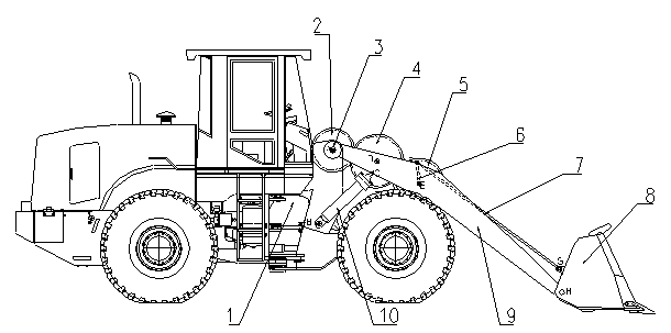
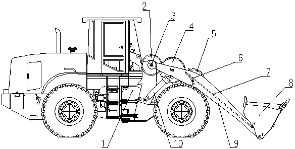
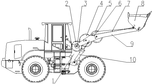
[0015] Such as figure 2 As shown in —5, the first gear 2 is locked, the boom cylinder 10 is kept locked, so that the boom 9 and the bucket 8 are fixed relative to the vehicle body, the loader vehicle body 1 moves forward, and the bucket 8 realizes loading state, such as figure 2 shown. Keep the boom oil cylinder 10 locked, and then drive the first gear 2 counterclockwise to rotate a certain angle around the mandrel 3, the third gear 5 also rotates counterclockwise due to the meshing relationship between the three gears, and the rocker on the third gear 5 The arm 6 also rotates counterclockwise, pulling the connecting rod 7 to make the parallel four-bar mechanism swing counterclockwise, and the bucket 8 realizes the end material state, such as image 3 shown. Lock the first gear 2, the piston rod of the boom cylinder 10 is extended, and the boom 9 is lifted with the bucket 8, the first gear 2, the second gear 4 and the third gear 5 form a planetary gear train, then the fir...


PUM


Abstract

The invention relates to a working device of a synchronous transmission gear type loader, and belongs to the field of industrial and mineral machinery. The working device is characterized in that one end of the movable arm of the loader is mounted at a first fixed point at the front part of a vehicle body through a mandrel, the other end of the movable arm is articulated at an eighth fixed point at the bottom end of a bucket, the bottom end of the oil cylinder of the movable arm is articulated at a second fixed point on the vehicle body, the top end of a piston rod is articulated at a third fixed point on the movable arm, a first gear is mounted on the mandrel, a second gear joggled with the first gear is mounted at a fourth fixed point on the movable arm, a third gear joggled with the second gear is mounted at the fifth fixed point on the movable arm, one end of a connecting rod is articulated at a sixth fixed point on the side of the third gear, the other end of the connecting rod is articulated at a seventh fixed point at the upper part of the bucket, the connection between the fifth fixed point and the sixth fixed point is supposed to form a rocker, connecting lines among the fifth fixed point, the sixth fixed point, the seventh fixed point and the eighth fixed point form a parallel four-bar linkage, and the modulus and tooth quantity of the first gear and the third gear are identical.

Description

technical field [0001] The invention belongs to the technical field of construction machinery and mining machinery, and in particular relates to a working device of a synchronous transmission gear loader. Background technique [0002] At present, most of the working devices used by loaders at home and abroad are reverse six-bar linkage mechanisms, which are composed of booms, boom cylinders, pull rods, rocker arms and rocker cylinders. When the bucket shovels, the rocker cylinder pushes the rocker The arm drives the pull rod to lift the bucket, and when the piston rod of the boom cylinder is extended, the bucket must be lifted in conjunction with the extension of the piston rod of the rocker cylinder to keep the bucket in a flat state; When the size of the large rocker arm cylinder and the boom is used to increase the unloading height of the bucket, the hinge point of the rocker arm seat beam must be determined by "trial and error", which will bring inconvenience to the lift...

Claims


Application Information

Patent Timeline
Patent Type & Authority Patents(China)
IPC IPC(8): E02F3/34E02F3/38E02F3/42
Inventor 赵春江杨志军黄庆学杨广科陈今良张艳峰
Owner TAIYUAN UNIVERSITY OF SCIENCE AND TECHNOLOGY
Learn More