Backlight module

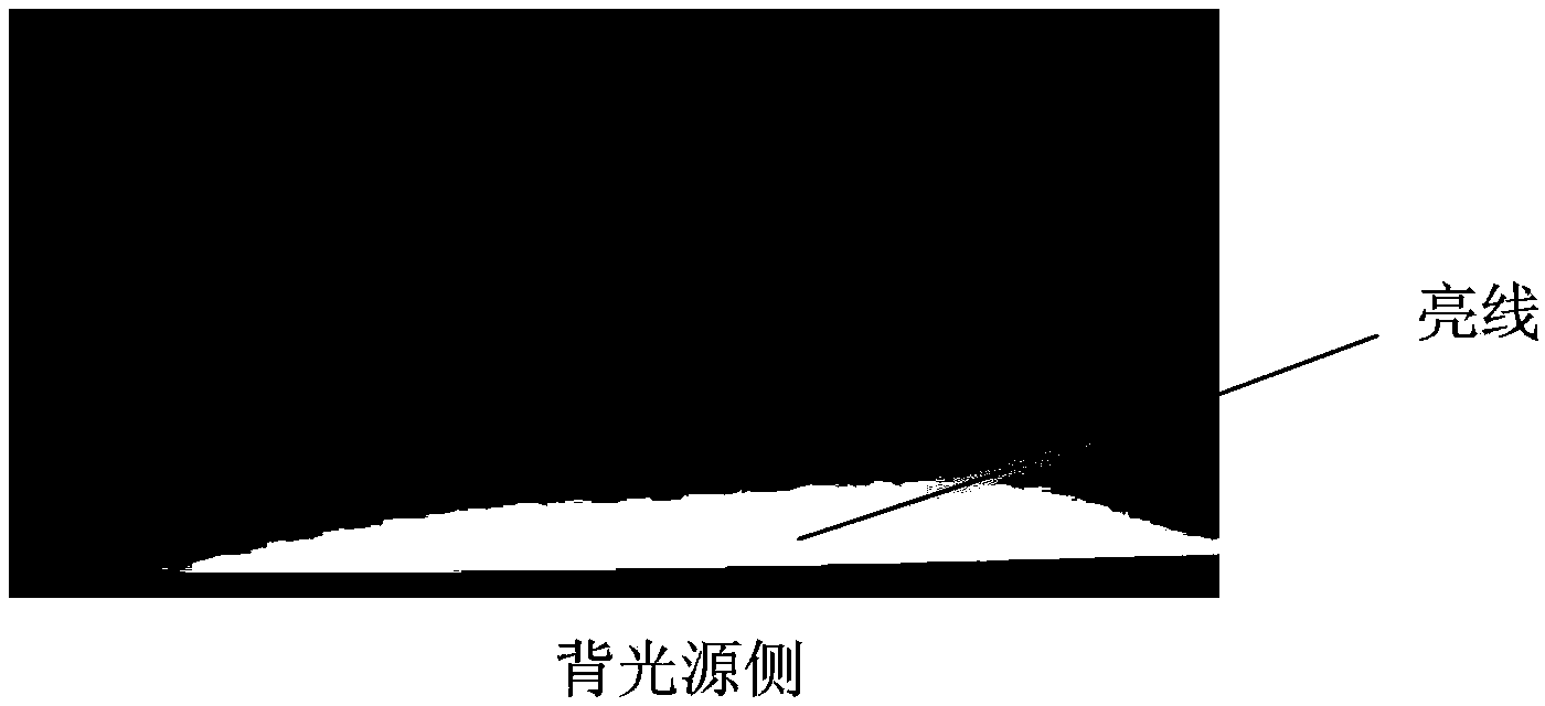
A backlight module and backlight technology, applied in optics, light guides, light sources, etc., can solve the problems of LED light source 200 brightness loss and escape, and achieve the effect of avoiding brightness loss and improving utilization.

Active Publication Date: 2014-10-29
TCL CHINA STAR OPTOELECTRONICS TECH CO LTD
View PDF5 Cites 1 Cited by
  • Summary
  • Abstract
  • Description
  • Claims
  • Application Information

AI Technical Summary

Problems solved by technology

see figure 2 , this is because part of the light emitted by the LED light source 200 will be incident on the plastic frame 600. For this reason, the existing technical solution is to make the plastic frame 600 relative to the LED light source 200, the light guide plate 300 and the optical film 500. The reflective layer 700 is set on the position to reflect the light incident on the plastic frame 600 back, but some light will still be reflected into the gap between the light guide plate 300 and the plastic frame 600, thus escaping into bright lines, causing the LED light source 200 to emit light. loss of brightness of the light

Method used


Image

  • Backlight module
  • Backlight module
  • Backlight module

Examples


Embodiment Construction

[0023] In order to further illustrate the technical means adopted by the present invention and its effects, the following describes in detail in conjunction with preferred embodiments of the present invention and accompanying drawings.

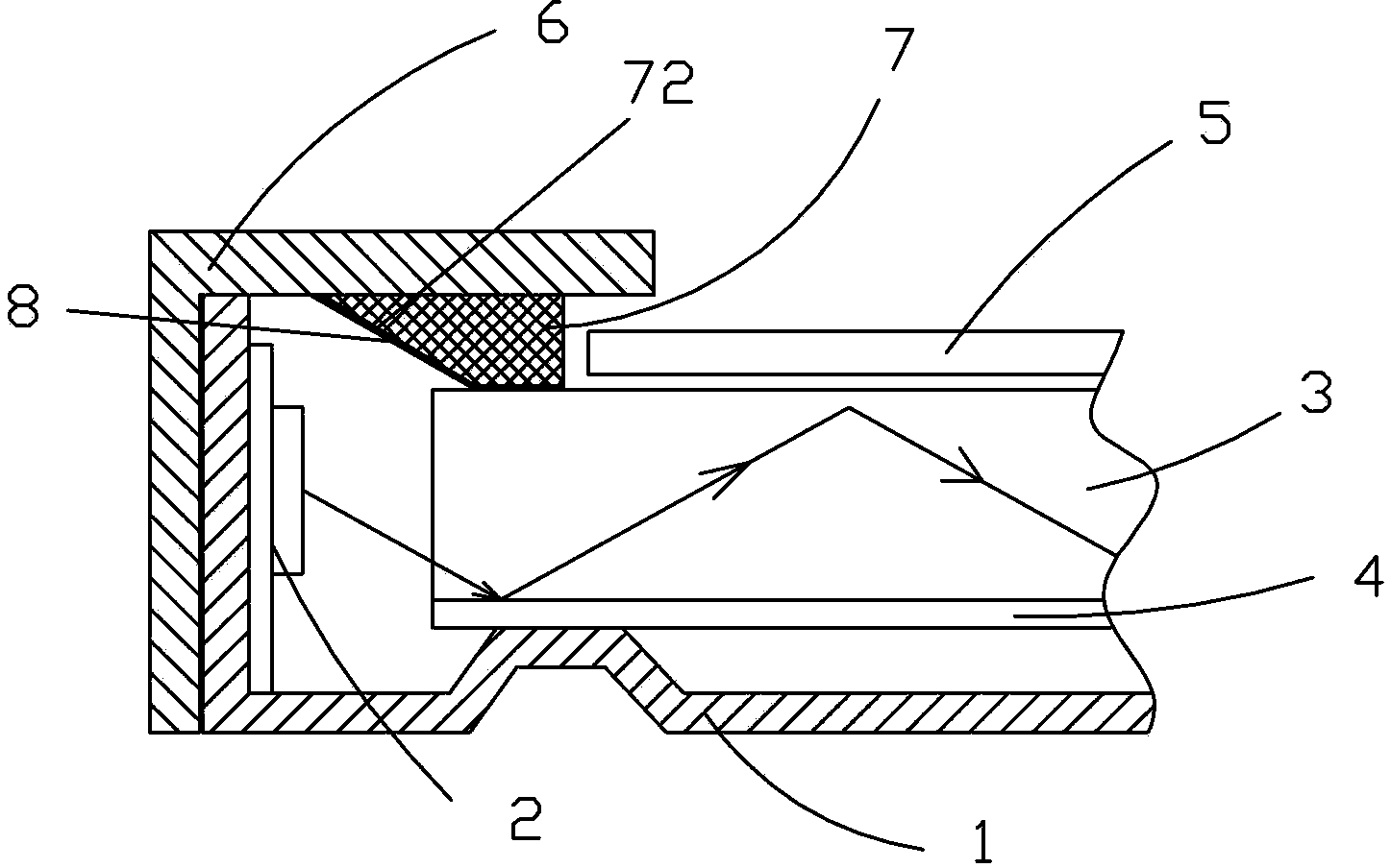
[0024] see image 3 , the present invention provides a backlight module, comprising: a backplane 1, a backlight 2 disposed in the backplane 1, a light guide plate 3 disposed in the backplane 1 and opposite to the backlight 2, and a light guide plate 3 disposed between the light guide plate 3 and the backlight 2 The reflection sheet 4 between the backplane 1, the optical film group 5 arranged on the light guide plate 3, the plastic frame 6 arranged on the backplane 1, and the light guide plate 3 and the plastic frame 6 and opposite to the backlight 2, the retaining wall 7 is provided, and the retaining wall 7 has an inclined surface 72 on the side close to the backlight source 2, and a reflective layer 8 is provided on the inclined surface 72. ...


PUM


Abstract

Provided is a backlight module, comprising a back plate (1), a backlight source (2) disposed in the back plate (1), a light guide plate (3) disposed opposing to the backlight source (2) in the back plate (1), a reflective piece (4) disposed between the light guide plate (3) and the back plate (1), an optical membrane set (5) disposed on the light guide plate (3), an adhesive frame (6) disposed on the back plate (1), and a retaining wall (7) disposed opposing to the backlight source (2) between the light guide plate (3) and the adhesive frame (6); the retaining wall (7) is provided with an inclined surface (72) on the side adjacent to the backlight source (2); the inclined surface (72) is provided with a reflective layer (8) thereon. By arranging the retaining wall (7) having a reflective layer (8) at a position opposing to the backlight source (2) between the adhesive frame (6) and the light guide plate (3), the light emitted onto the retaining wall (7) is reflected into the light guide plate (3), therefore the present invention avoids forming a bright line due to the light reflected out from a gap between the optical membrane set (5) and the light guide plate (3), and well solves the problem of bright line on the incident side of a side-incident backlight module, thus having higher light coupling efficiency while improving the luminance of the light guide plate (3), avoiding luminance loss of the light emitted by an LED light source, and improving LED light source utilization rate.

Description

technical field [0001] The invention relates to the field of liquid crystal display, in particular to a backlight module for improving the brightness of a light guide plate. Background technique [0002] A liquid crystal display (LCD, Liquid Crystal Display) has many advantages such as a thin body, power saving, and no radiation, and has been widely used. Most of the liquid crystal display devices currently on the market are backlight liquid crystal display devices, which include a liquid crystal panel and a backlight module. The working principle of the liquid crystal panel is to place liquid crystal molecules between two parallel glass substrates. There are many vertical and horizontal small wires between the two glass substrates. The direction of the liquid crystal molecules is controlled by electrifying or not, and the light of the backlight module is refracted. Come out to generate the picture. Since the liquid crystal panel itself does not emit light, the light sourc...

Claims


Application Information

Patent Timeline
Patent Type & Authority Patents(China)
IPC IPC(8): F21S8/00F21V13/00G02F1/13357F21Y101/02
CPCG02F1/133608G02F1/1333G02F2202/28G02F1/133605G02B6/0001G02B6/0055G02B6/0091
Inventor 黄建发
Owner TCL CHINA STAR OPTOELECTRONICS TECH CO LTD
Why Eureka
Try Eureka