Image display method, device, electronic device and readable storage medium

An image display and image technology, applied in the fields of electronic equipment, readable storage media, image display methods, and devices, can solve problems such as poor display effect and poor backlight control effect, and achieve poor display effect and backlight improvement Poor control effect, effect of boosting brightness

Active Publication Date: 2021-06-08
ONEPLUS TECH SHENZHEN
View PDF9 Cites 0 Cited by
  • Summary
  • Abstract
  • Description
  • Claims
  • Application Information

AI Technical Summary

Problems solved by technology

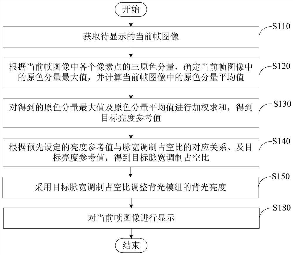
[0003] In view of this, the purpose of this application is to provide an image display method, device, electronic equipment and readable storage medium, which calculates the actual value of the current frame image according to the maximum value of the primary color component and the average value of the primary color component in the current frame image. The target brightness reference value corresponding to the brightness, and then the target brightness reference value adjusts the backlight brightness, so as to effectively improve the problem of poor backlight control effect and poor display effect caused by the large deviation between the calculated brightness and the actual brightness of the frame image

Method used

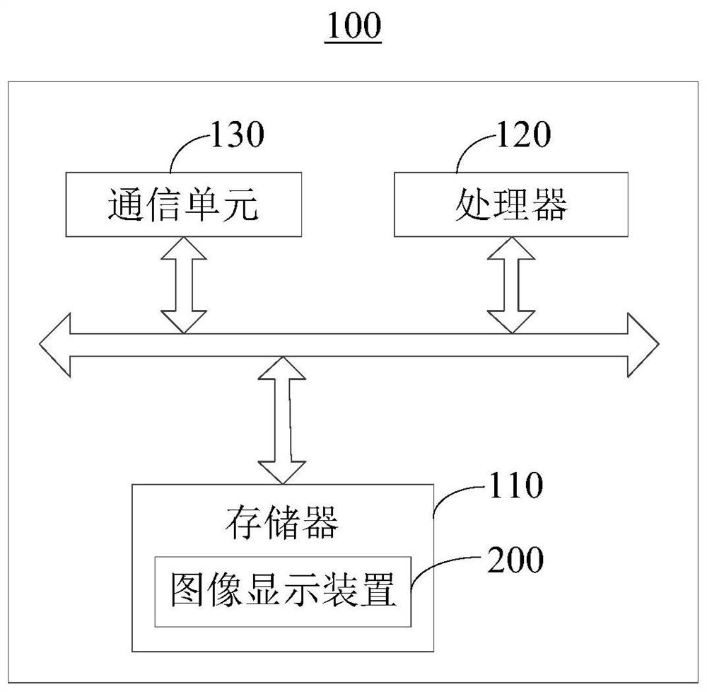

Image

  • Image display method, device, electronic device and readable storage medium
  • Image display method, device, electronic device and readable storage medium
  • Image display method, device, electronic device and readable storage medium

Examples


Embodiment Construction

[0055] The following will clearly and completely describe the technical solutions in the embodiments of the present application with reference to the accompanying drawings in the embodiments of the present application. Obviously, the described embodiments are only some of the embodiments of the present application, not all of them. The components of the embodiments of the application generally described and illustrated in the figures herein may be arranged and designed in a variety of different configurations.

[0056] Accordingly, the following detailed description of the embodiments of the application provided in the accompanying drawings is not intended to limit the scope of the claimed application, but merely represents selected embodiments of the application. Based on the embodiments of the present application, all other embodiments obtained by those skilled in the art without making creative efforts belong to the scope of protection of the present application.

[0057] I...


PUM


Abstract

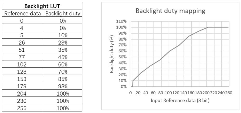
Embodiments of the present application provide an image display method, device, electronic equipment, and readable storage medium, which relate to the field of image display technologies. The method includes: obtaining the maximum value of the primary color components and the average value of the primary color components in the current frame image according to the three primary color components of each pixel in the current frame image to be displayed; performing weighted summation on the obtained above-mentioned values ​​to obtain a target brightness reference value ;According to the preset corresponding relationship between the brightness reference value and the pulse width modulation duty ratio, and the target brightness reference value, the target pulse width modulation duty ratio is obtained; the backlight brightness of the backlight module is adjusted by using the target pulse width modulation duty ratio , and display the current frame image. Therefore, adjusting the backlight brightness according to the target brightness reference value corresponding to the actual brightness of the current frame image can effectively improve the poor backlight control effect and poor display effect caused by the large deviation between the calculated brightness and the actual brightness of the frame image. good question.

Description

technical field [0001] The present application relates to the technical field of screen display, and in particular, to an image display method, device, electronic equipment, and readable storage medium. Background technique [0002] At present, the backlight control of a display device (for example, a liquid crystal television) generally first obtains the brightness of a frame image according to a brightness equation, and then adjusts the brightness of the backlight according to the brightness. Wherein, the brightness equation is: Y=0.30R+0.59G+0.11B. However, in some cases, there is a large deviation between the luminance calculated by the above method and the actual luminance of the frame image, which will lead to poor control effect of backlight luminance and poor display effect. For example, the R (red) component and G (green) component of a frame image are very small, and the B (blue) component is very large, and the actual brightness of the frame image is much greater...

Claims


Application Information

Patent Timeline
Patent Type & Authority Patents(China)
IPC IPC(8): G09G3/34
CPCG09G3/3406
Inventor 罗荣荣
Owner ONEPLUS TECH SHENZHEN
Why Eureka
Try Eureka