High-power LED (light emitting diode) heat radiator

An LED radiator, high-power technology, applied in lighting and heating equipment, cooling/heating devices for lighting devices, lighting devices, etc., can solve the problems of insufficient heat dissipation, difficult processing of LED radiators, and large size.

Inactive Publication Date: 2012-11-07
NORTH CHINA ELECTRIC POWER UNIV (BAODING)
View PDF3 Cites 6 Cited by
  • Summary
  • Abstract
  • Description
  • Claims
  • Application Information

AI Technical Summary

Problems solved by technology

[0006] The purpose of the present invention is to solve the problems of high processing difficulty, large size, and insufficient heat dissipation of the LED radiator described in the background technology, and provide a high-power LED heat dissipation by using a heat conduction cavity filled with heat conduction oil to obtain heat, and using an oscillating flow heat pipe to dissipate heat The device is characterized in that 4 to 16 annular fins 2 are fixed horizontally on the outer wall of the cylindrical heat conduction cavity 1, and a divergent oscillating flow heat pipe 3 is fixed coaxially on each fin 2, and the fins There is a wire hole 4 on the sheet 2, and the wire holes 4 on all the fins 2 are on the same vertical line, and the heating section of the divergent oscillating flow

Method used


Image

  • High-power LED (light emitting diode) heat radiator
  • High-power LED (light emitting diode) heat radiator
  • High-power LED (light emitting diode) heat radiator

Examples


Embodiment Construction

[0025] The present invention will be further described below in conjunction with the accompanying drawings and specific examples.

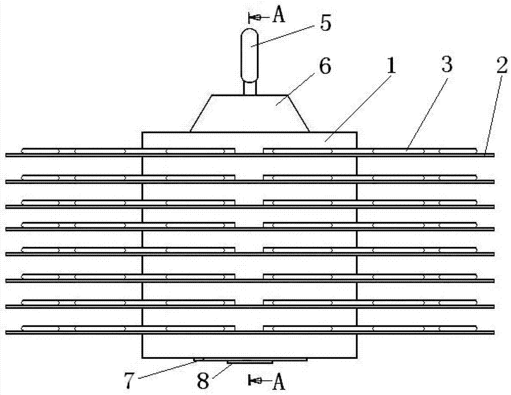
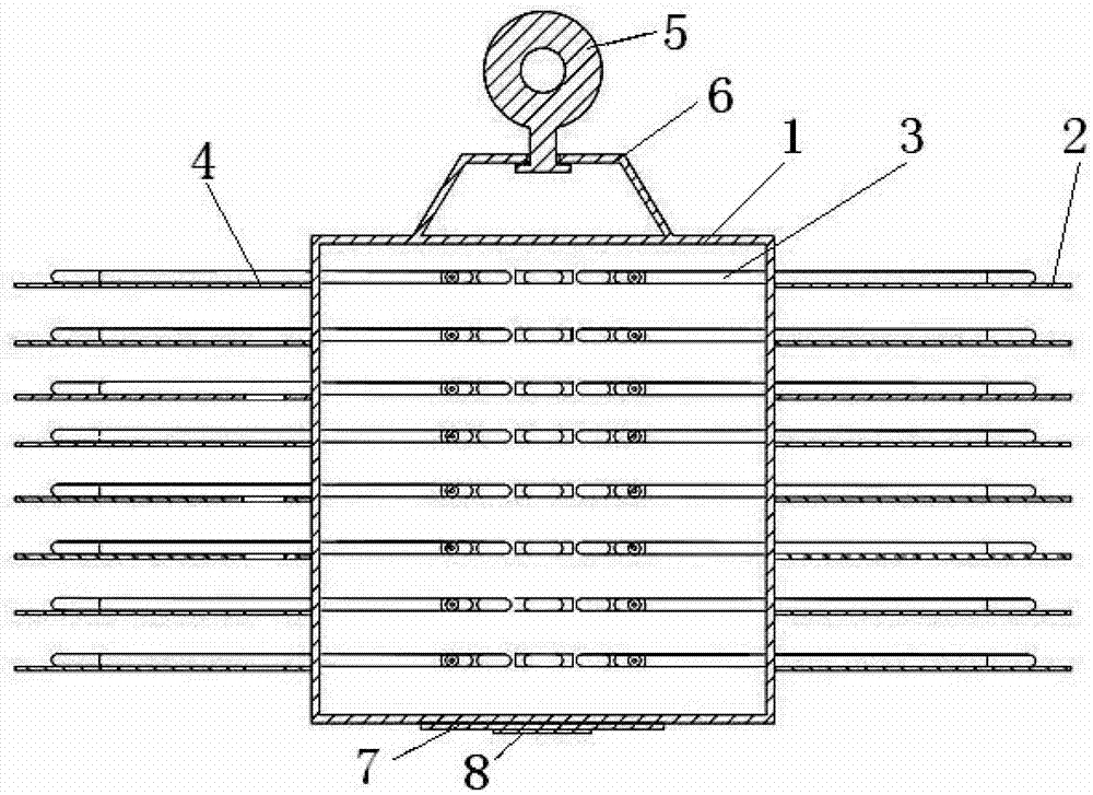
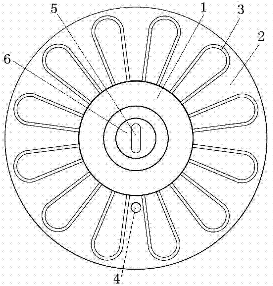
[0026] The structure of high-power LED radiator is as follows: figure 1 , image 3 and Figure 4 shown. 8 circular copper fins 2 are fixed horizontally on the outer wall of the cylindrical heat conduction cavity 1, and a divergent oscillating flow heat pipe 3 is coaxially welded on each fin 2, and the divergent oscillating flow heat pipe 3 is 24 An elbow petal-shaped single-circuit oscillating flow heat pipe, and a divergent oscillating flow heat pipe 3. The material of the capillary is copper tube. There is a wire hole 4 on the fin 2, and the wire holes 4 on all the fins 2 are on the same vertical line, and the LED power line passes therethrough. The heating section of the divergent oscillating flow heat pipe 3 passes through the outer wall of the heat conduction cavity 1 and is placed in the cavity of the heat conduction cavity 1, such as ...


PUM


Abstract

The invention belongs to the technical field of high heat flux density electronic elements and relates to a high-power LED (light emitting diode) heat radiator, wherein an outer wall of a cylindrical heat conduction cavity is fixedly connected with 4-16 ring-shaped fins; one divergent oscillating-flow heat pipe is coaxially and fixedly connected to each fin; a heating section of the divergent oscillating-flow heat pipe is arranged in a cavity body of the heat conduction cavity after passing through the outer wall of the heat conduction cavity; the divergent oscillating-flow heat pipe is fixedly and hermetically connected with the outer wall of the heat conduction cavity; a round LED base is coaxially and fixedly connected to the lower end face of the heat conduction cavity; an LED chip is fixedly connected to the centre of the LED base; a sealed container is used as the heat conduction cavity, and heat conduction media are filled in the heat conduction cavity. With the adoption of the united running of the divergent oscillating-flow heat pipe and the heat conduction cavity filled with low boiling-point heat conduction medium or heat conduction oil, heat generated by the LED is released in time, so that the heat radiator is an efficient, portable and beautiful high-power LED heat radiator which is suitable for the radiation of high heat flux density electronic elements and particularly suitable for the heat radiation of high-power LEDs.

Description

technical field [0001] The invention belongs to the technical field of high heat flux electronic components, in particular to a high-power LED radiator. Background technique [0002] LED (Light Emitting Diode, Light Emitting Diode), as a new light-emitting element, is being vigorously advocated and promoted at home and abroad due to its advantages such as energy saving, environmental protection, high brightness, and low heat. The surface temperature of the LED will continue to rise with the accumulation of heat generated during work, especially for high-power LEDs, the problem of heat dissipation is particularly important. If the heat generated cannot be taken away in time, it will affect its luminous efficiency and accelerate the speed of the chip. Aging shortens its service life. At present, high-power LED products on the market usually adopt the method of adding fins on the substrate to dissipate heat. With the increase of LED power, the size of the heat dissipation devi...

Claims


Application Information

Patent Timeline
IPC IPC(8): F21V29/00F21Y101/02F21V29/51
Inventor 冼海珍王川川杨勇平杜小泽刘登瀛
Owner NORTH CHINA ELECTRIC POWER UNIV (BAODING)
Why Eureka
Try Eureka