X-ray source for wide-field X-ray phase-contrast imaging

A phase-contrast imaging and X-ray technology, which is applied in the X-ray tube parts, X-ray tube electrodes, X-ray tube target geometry, etc., can solve the limitation of the imaging field of view of the array structure X-ray source, which is difficult to apply to large Field of view X-ray phase contrast imaging, complex source grating manufacturing and other issues, to avoid process problems, high spatial coherence, and low manufacturing costs

Active Publication Date: 2012-11-07
SHENZHEN UNIV
View PDF2 Cites 7 Cited by
  • Summary
  • Abstract
  • Description
  • Claims
  • Application Information

AI Technical Summary

Problems solved by technology

[0006] The technical problem to be solved by the present invention is that in the way of using the source grating in the prior art, the manufacturing of the source grating is complicated and difficult, and the imaging field of view of the X-ray source with an array structure is limited, so it is difficult to apply it in a large field of view. Defects in field X-ray phase contrast imaging, providing a large field of view X-ray phase contrast imaging that can be applied in large field of view X-ray phase contrast imaging, overcomes the field of view limitation of the array structure anode, has low manufacturing cost, and is simple and reliable in manufacturing process. X-ray Sources for Radiographic Phase Contrast Imaging

Method used


Image

  • X-ray source for wide-field X-ray phase-contrast imaging
  • X-ray source for wide-field X-ray phase-contrast imaging
  • X-ray source for wide-field X-ray phase-contrast imaging

Examples


Embodiment 1

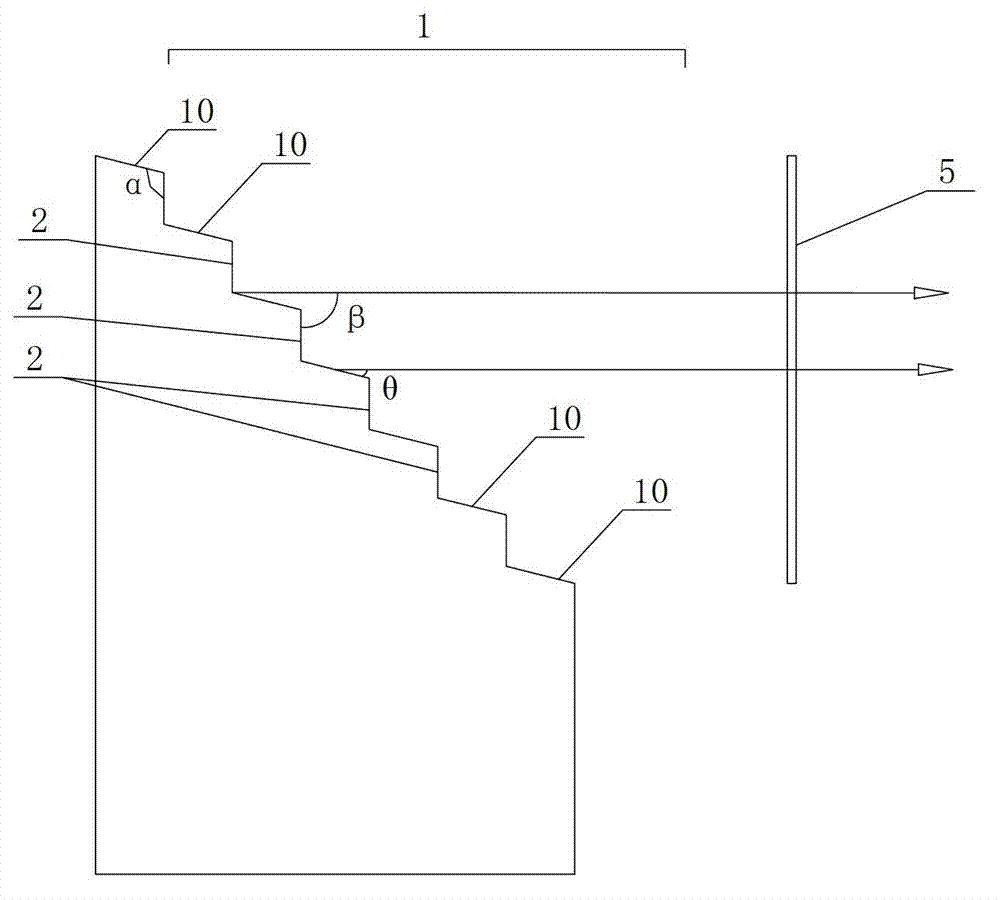
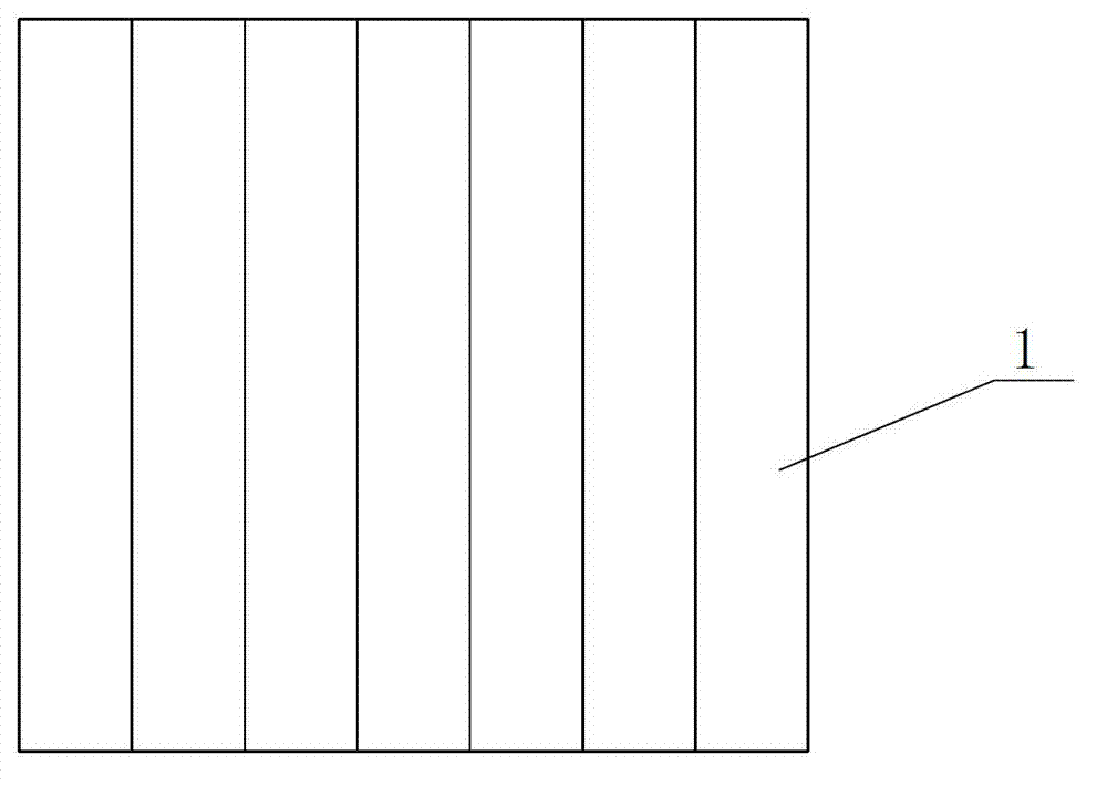
[0032] Embodiment 1, as figure 1 , 2As shown, the anode target of the present invention is a cylinder with an integrated structure, that is, the anode target does not adopt the array arrangement method in the prior art, but an integral and non-separated cylinder structure. The anode target is a cylindrical structure made of common anode materials used to generate X-rays, such as tungsten, molybdenum and other high-Z element materials. The anode target is manufactured by micro-nano processing technology, such as etching technology and high-precision micro-machining method.

[0033] The top of the anode target is provided with an emission surface 1 for emitting X-rays. The electron beam emitted by the electron source bombards the emission surface 1 of the anode target, and the emission surface 1 responds to emit X-rays. The emitted X-rays pass through the X-ray exit window 5 Injection, irradiating the object for X-ray phase contrast imaging. The emitting surface 1 is composed...

Embodiment 2

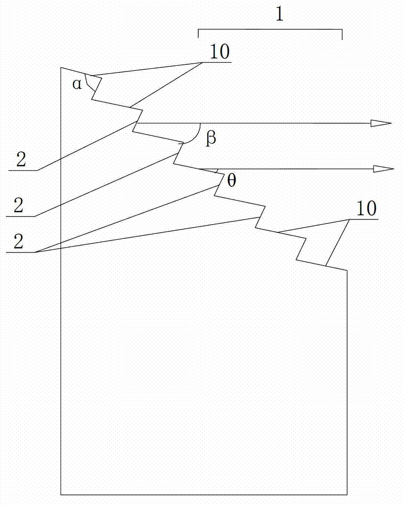
[0038] Example 2, such as image 3 , 4 As shown, this embodiment is an implementation manner improved on the basis of embodiment 1. Wherein the emission surface 1 of the anode target is also composed of a plurality of inclined emission surface units 10 arranged continuously in a step shape and parallel to each other, and the projection of the emission surface 1 on the vertical direction of the principal optical axis of the emission surface of the anode target is a continuous Overall. The difference between this embodiment and Embodiment 1 is: the included angle β between the side walls 2 between the steps between the adjacent emitting surface units 10 and the main optical axis of the anode target emitting surface 1 is selected to be greater than 90°, that is The sidewalls 2 between the steps are bent toward the back of the emission surface 1 of the anode target, then viewed from the electron beam emission direction, the sidewalls 2 between the steps between the adjacent emis...

Embodiment 3

[0040] Example 3, such as Figure 5 , 6 As shown, this embodiment is another improved implementation on the basis of embodiment 1. In addition to the projection of a plurality of emitting surface units 10 in the vertical direction of the main optical axis of the anode target emitting surface in Embodiments 1 and 2 to form a continuous whole, the emitting surface 1 of the present embodiment is on the anode target emitting surface. The projections in the vertical direction of the main optical axis are arranged in parallel at intervals, but the gap between the projections of adjacent emitting surface units 10 is required to be 10-70 microns. The projection interval arrangement is formed by providing interval grooves 3 between the emitting surface units 10 . The spacing groove 3 is specifically arranged between one side edge of the emitting surface unit 10 and the side wall 2 between the steps, that is, the lateral position of the spacing groove 3 is between the emitting surface...


PUM


Abstract

The invention discloses an X-ray source for wide-field X-ray phase-contrast imaging. The X-ray source comprises an electronic source for emitting electronic beams and an anode target for emitting X rays in response to incidence of the electronic beams, wherein the anode target is an integrated column body; an emission surface is formed at the top end of the anode target and consists of a plurality of stepwise distributed oblique emission surface units which are parallel to each other; the included angle alpha between the emission surface of the anode target and the inter-step side wall between the adjacent emission surface units is 50-120 degrees; and the included angle beta between the inter-step side wall and a principal optic axis of the emission surface of the anode target is not less than 90 degrees. The X-ray source for wide-field X-ray phase-contrast imaging can be applied to wide-field X-ray phase-contrast imaging, can overcome the field limitation of an anode of an array structure, and is low in manufacturing cost and simple and reliable in manufacturing process.

Description

technical field [0001] The invention belongs to the technical field of X-ray phase-contrast imaging, and relates to an X-ray source, in particular to an X-ray source for large-field X-ray phase-contrast imaging. Background technique [0002] X-ray imaging technology is a non-destructive testing technology that has been widely used in chemical, agricultural, biological, medical and security inspection fields. The physical mechanism of traditional X-ray imaging technology is to obtain the internal information of objects through different attenuation of X-rays passing through objects with different thicknesses and different material compositions. For substances with a large atomic number (such as heavy metals, human bones), a clear image can be obtained due to the large absorption of X-rays. However, for substances composed of light elements (such as C, H, O, N), such as soft tissues of the human body, living biological samples, optical fibers, solid deuterium-tritium fuel, ga...

Claims


Application Information

Patent Timeline
Patent Type & Authority Applications(China)
IPC IPC(8): H01J35/08H01J35/06
CPCH01J2235/086
Inventor 黄建衡杜杨牛憨笨郭金川刘鑫林丹樱
Owner SHENZHEN UNIV
Why Eureka
Try Eureka