X-ray source for wide-field X-ray phase-contrast imaging
A phase-contrast imaging and X-ray technology, which is applied in the X-ray tube parts, X-ray tube electrodes, X-ray tube target geometry, etc., can solve the limitation of the imaging field of view of the array structure X-ray source, which is difficult to apply to large Field of view X-ray phase contrast imaging, complex source grating manufacturing and other issues, to avoid process problems, high spatial coherence, and low manufacturing cost
- Summary
- Abstract
- Description
- Claims
- Application Information
AI Technical Summary
Problems solved by technology
Method used
Image
Examples
Embodiment 1
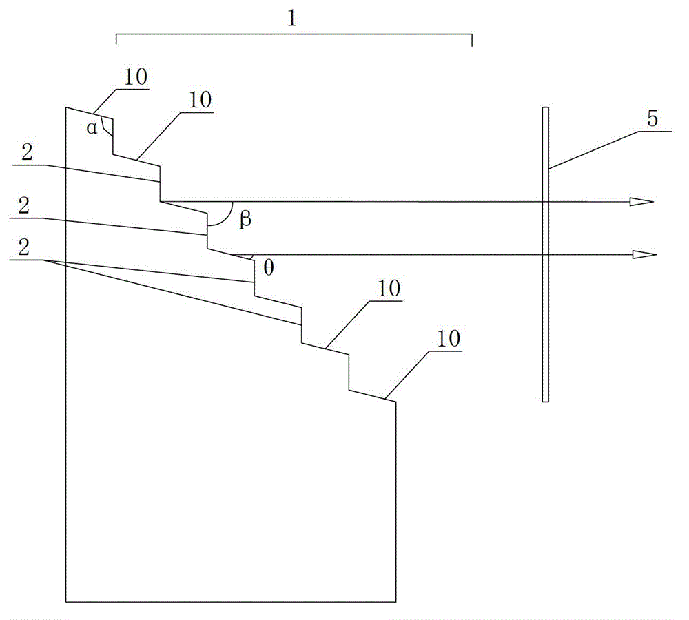
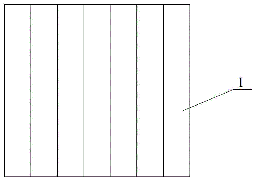
[0032] Embodiment 1, as figure 1 , 2As shown, the anode target of the present invention is a cylinder with an integrated structure, that is, the anode target does not adopt the array arrangement method in the prior art, but an integral and non-separated cylinder structure. The anode target is a cylindrical structure made of common anode materials used to generate X-rays, such as tungsten, molybdenum and other high-Z element materials. The anode target is manufactured by micro-nano processing technology, such as etching technology and high-precision micro-machining method.
[0033] The top of the anode target is provided with an emission surface 1 for emitting X-rays. The electron beam emitted by the electron source bombards the emission surface 1 of the anode target, and the emission surface 1 responds to emit X-rays. The emitted X-rays pass through the X-ray exit window 5 Injection, irradiating the object for X-ray phase contrast imaging. The emitting surface 1 is composed...
Embodiment 2
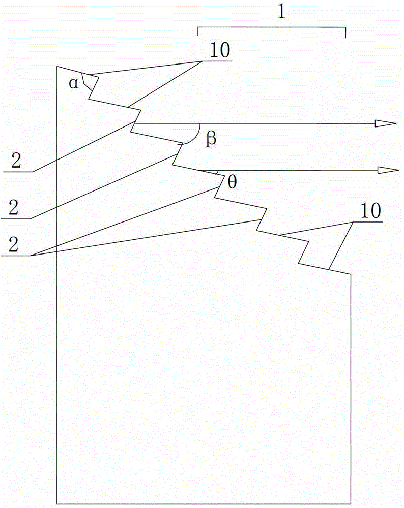
[0038] Example 2, such as image 3 , 4 As shown, this embodiment is an implementation manner improved on the basis of embodiment 1. Wherein the emission surface 1 of the anode target is also composed of a plurality of inclined emission surface units 10 arranged continuously in a step shape and parallel to each other, and the projection of the emission surface 1 on the vertical direction of the principal optical axis of the emission surface of the anode target is a continuous Overall. The difference between this embodiment and Embodiment 1 is: the included angle β between the side walls 2 between the steps between the adjacent emitting surface units 10 and the main optical axis of the anode target emitting surface 1 is selected to be greater than 90°, that is The sidewalls 2 between the steps are bent toward the back of the emission surface 1 of the anode target, then viewed from the electron beam emission direction, the sidewalls 2 between the steps between the adjacent emis...
Embodiment 3
[0040] Example 3, such as Figure 5 , 6 As shown, this embodiment is another improved implementation on the basis of embodiment 1. In addition to the projection of a plurality of emitting surface units 10 in the vertical direction of the main optical axis of the anode target emitting surface in Embodiments 1 and 2 to form a continuous whole, the emitting surface 1 of the present embodiment is on the anode target emitting surface. The projections in the vertical direction of the main optical axis are arranged in parallel at intervals, but the gap between the projections of adjacent emitting surface units 10 is required to be 10-70 microns. The projection interval arrangement is formed by providing interval grooves 3 between the emitting surface units 10 . The spacing groove 3 is specifically arranged between one side edge of the emitting surface unit 10 and the side wall 2 between the steps, that is, the lateral position of the spacing groove 3 is between the emitting surface...
PUM
 Abstract
Description
Claims
Application Information
 - R&D
- Intellectual Property
- Life Sciences
- Materials
- Tech Scout
- Unparalleled Data Quality
- Higher Quality Content
- 60% Fewer Hallucinations
Browse by: Latest US Patents, China's latest patents, Technical Efficacy Thesaurus, Application Domain, Technology Topic, Popular Technical Reports.
© 2025 PatSnap. All rights reserved.Legal|Privacy policy|Modern Slavery Act Transparency Statement|Sitemap|About US| Contact US: help@patsnap.com


