
Antenna impedance automatic matching device and method based on parasitic resonance frequency point

A parasitic resonance and automatic matching technology, applied in impedance networks, electrical components, multi-terminal-pair networks, etc., can solve the problems of increased design difficulty, difficulty in miniaturization, and bulky filters, achieving the effect of simple design and easy miniaturization

Active Publication Date: 2015-06-17
XIDIAN UNIV
View PDF2 Cites 0 Cited by
  • Summary
  • Abstract
  • Description
  • Claims
  • Application Information

AI Technical Summary

Problems solved by technology

[0006] 1) In a narrowband receiving system (such as GPS), the bandwidth of the antenna is very close to the bandwidth of the receiver. Due to the unavoidable spectrum leakage, the measurement signal transmitted near the frequency point will affect the normal operation of the receiver
[0007] 2) Since the adjacent frequency point is very close to the receiving frequency point, in order to isolate and eliminate the signal of the adjacent frequency point, a very highly selective filter is required, which is usually achieved with a high-Q cavity, which will increase the difficulty of design, especially in In the low frequency band, the filter is bulky and difficult to miniaturize

Method used


Image

  • Antenna impedance automatic matching device and method based on parasitic resonance frequency point
  • Antenna impedance automatic matching device and method based on parasitic resonance frequency point
  • Antenna impedance automatic matching device and method based on parasitic resonance frequency point

Examples


Embodiment Construction

[0040] The present invention will be further described below in conjunction with embodiment:

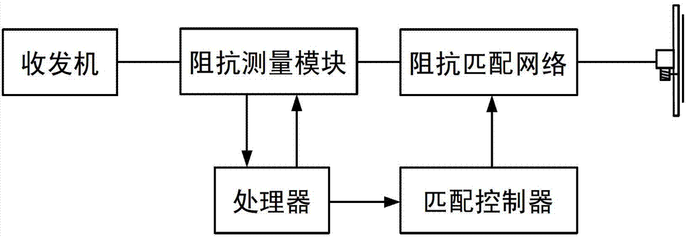
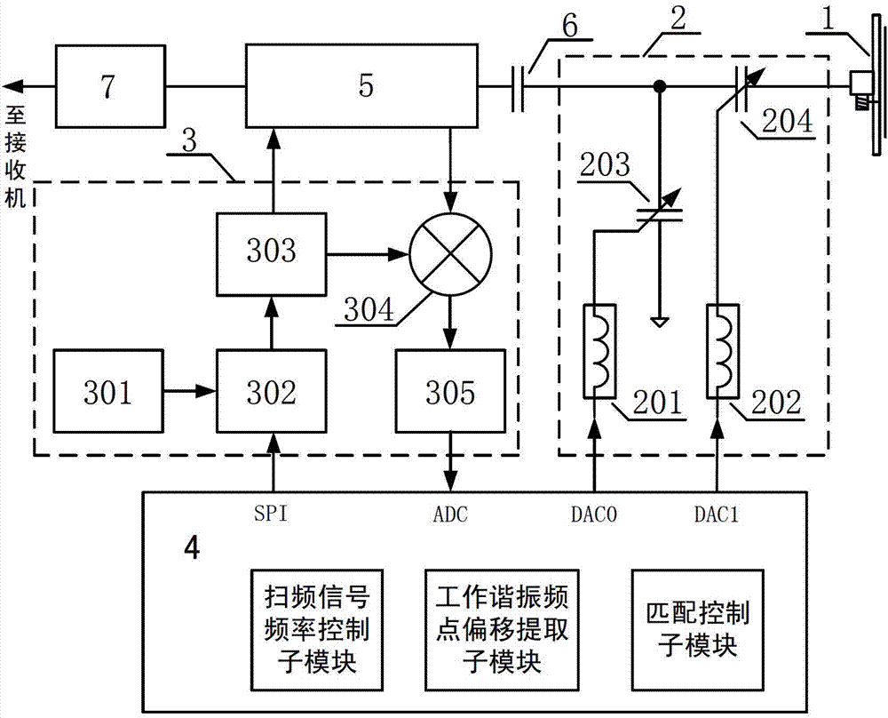
[0041] refer to figure 2 , the present invention is composed of an antenna 1, an ESC matching module 2, an antenna parasitic resonant frequency point reflection measurement module 3, a processing and control module 4, a coupler module 5, a DC blocking capacitor 6, and a filter 7. Antenna parasitic resonant frequency point reflection measurement module 3 is connected with coupling module 5 and processing control module 4 respectively, is used for transmitting antenna parasitic resonant frequency point sweep signal to coupling module 5, and the antenna parasitic resonant frequency point reflection of coupling module 5 output The signal is subjected to synchronous detection and low-pass filtering to obtain the amplitude signal R of the spurious frequency point sweep reflection coefficient m , the reflection coefficient magnitude signal R m Input to the processing and control module 4...


PUM


Abstract

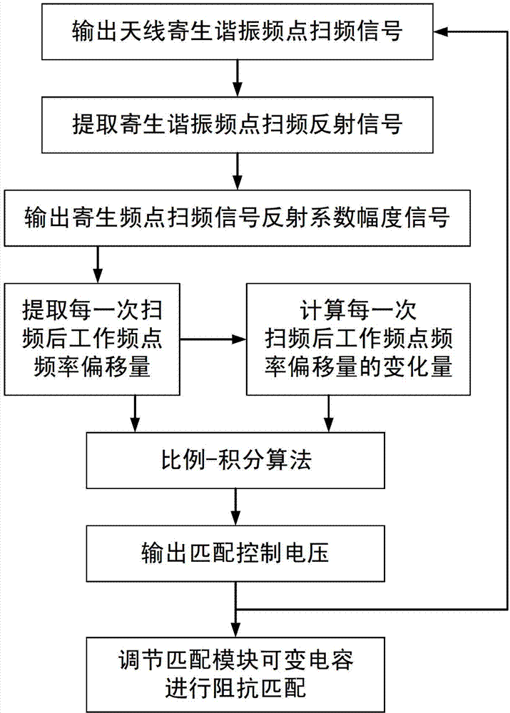
The invention discloses an antenna impedance automatic matching device based on a parasitic resonance frequency point. The antenna impedance automatic matching device comprises an antenna (1), an electrically tunable matching module (2), an antenna parasitic resonance frequency point reflection measurement module (3), a processing and control module (4), a coupler module (5), a blocking capacitor (6) and a filter (7), wherein the antenna parasitic resonance frequency point reflection measurement module (3) transmits an antenna parasitic resonance frequency point frequency-sweeping signal to the coupler module (5), performs synchronous detection and low-pass filter on a reflecting signal which is output by the coupler module (5), and outputs a reflection coefficient amplitude signal; and the processing and control module (4) extracts the offset and variation of an antenna operation resonance frequency point after frequency is swept at each time according to the reflection coefficient amplitude signal, generates matched control voltage and controls the electrically tunable matching module (2) to realize automatic matching of antenna impedance. The antenna impedance automatic matching device has the advantages that the operation resonance frequency point offset of a single-receiving antenna can be compensated, and an effective gain of the single-receiving antenna is improved.

Description

technical field [0001] The invention belongs to the technical field of antennas, and in particular relates to automatic antenna impedance matching, which can be used to compensate the change of single-receiving antenna impedance under the coverage of time-varying media, improve the standing wave ratio of the working frequency point of the antenna, and reduce the impedance mismatch between the single-receiving antenna and the receiving system. Improve the receiving performance of the receiving system. Background technique [0002] When the temperature and medium around the antenna change, the impedance characteristics of the antenna will change with the environment, which will lead to the shift of the resonant frequency of the antenna and the deterioration of the standing wave ratio at the operating frequency, and the impedance of the antenna and the receiving system will be lost. If it is configured, the actual gain of the antenna will be reduced, resulting in the weakening ...

Claims


Application Information

Patent Timeline
Patent Type & Authority Patents(China)
IPC IPC(8): H03H7/38
Inventor 李小平白博文秦永强谢楷石磊刘彦明
Owner XIDIAN UNIV
Learn More