
An electronic device and an antenna device

An electronic device and antenna technology, applied in the electronic field, can solve the problem of poor signal receiving ability of the antenna, and achieve the effect of increasing product cost and increasing product volume

Active Publication Date: 2019-03-29
LENOVO (BEIJING) LTD
View PDF6 Cites 0 Cited by
  • Summary
  • Abstract
  • Description
  • Claims
  • Application Information

AI Technical Summary

Problems solved by technology

[0006] An embodiment of the present invention provides an electronic device and an antenna device, which are used to solve the technical problem that the electronic device has a poor ability to receive signals under the premise of meeting the requirements of small-volume design or low-cost design in the prior art. Under the premise of meeting the requirements of small-volume design or low-cost design, the technical effect of improving the ability of the antenna to receive signals

Method used


Image

  • An electronic device and an antenna device
  • An electronic device and an antenna device
  • An electronic device and an antenna device

Examples


Embodiment 1

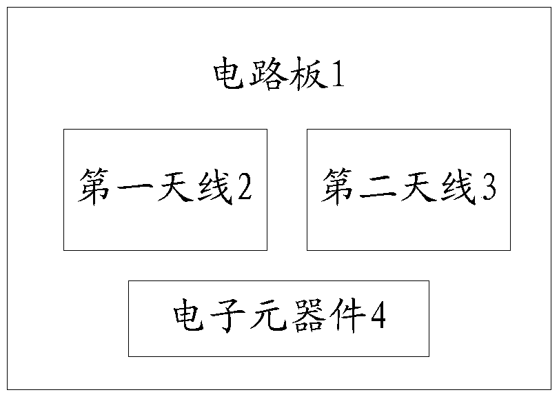
[0056] Please refer to figure 1 , is a schematic structural diagram of an electronic device provided in an embodiment of the present application, including a circuit board 1, an electronic component 4, a first antenna 2, and a second antenna 3, wherein the electronic component 4 is arranged on the circuit board 1, and the second An antenna 2 and a second antenna 3 are arranged at different positions in the circuit board 1, and the number of electronic components 4 is at least one. In practice, the number of electronic components 4 can be selected according to actual needs. For example, the number of electronic components 4 may be 1, 2, or 10, etc., which is not limited here. In practical applications, the type of electronic component 4 may be a CPU, or a memory, or other types of electronic devices that generate noise when in a running state, and there is no limitation here.

[0057] In practical applications, the electronic device can be a mobile phone, a small personal comp...

Embodiment 2

[0067] Based on the same inventive concept as the first embodiment of the present application, the second embodiment of the present application also provides an antenna device, please refer to Figure 4 , the antenna assembly includes:

[0068] The first antenna 5 is arranged on the first position of the circuit board of an electronic device, and is used for sending and receiving communication data signals between the electronic device and other electronic devices;

[0069] The second antenna 6 is arranged at a second position on the circuit board different from the first position;

[0070] Wherein, the second antenna can be used to couple the noise signal generated by the at least one electronic component disposed on the circuit board.

[0071] In practical applications, the above-mentioned electronic equipment can be a mobile phone, a small personal computer (i.e. a small PC, Personal Computer), or a tablet computer. Of course, it can also be other electronic equipment that...


PUM


Abstract

The invention discloses electronic equipment and an antenna apparatus. The electronic equipment comprises a circuit board, at least an electronic component arranged on the circuit board, a first antenna arranged at a first position of the circuit board and used for transmitting and receiving communication data signals between the electronic equipment and other electronic equipment, and a second antenna arranged at a second position different from the first position of the circuit board, and the second antenna can be used for coupling noise signals generated by the at least one electronic component.

Description

technical field [0001] The invention relates to the field of electronic technology, in particular to an electronic device and an antenna device. Background technique [0002] With the continuous development of Internet technology and the continuous popularization of electronic devices such as mobile phones and small personal computers, people's lifestyles have also undergone great changes. [0003] Some electronic components in electronic equipment, such as CPU, memory, etc., will generate a lot of in-band noise when they work at a certain frequency, and these noises will be received by the transceiver antenna in the electronic equipment, thus affecting the ability of the transceiver antenna to receive useful signals , in the prior art, in order to solve the above problems, it is mainly by increasing the distance between the transmitting and receiving antenna and the noise-generating components, or adding absorbing materials in the electronic equipment. [0004] However, in...

Claims


Application Information

Patent Timeline
Patent Type & Authority Patents(China)
IPC IPC(8): H01Q1/52H01Q21/00
Inventor 张露曹新张亚利
Owner LENOVO (BEIJING) LTD
Learn More