Heat radiator

A heat dissipation device and self-radiation technology, which is applied in the direction of cooling/ventilation/heating transformation, etc., can solve the problems of small heat dissipation area of ​​fin group, short time between airflow and heat dissipation fins, heat exchange, etc.

Inactive Publication Date: 2012-11-07
FURUI PRECISE COMPONENT (KUNSHAN) CO LTD +1
View PDF7 Cites 3 Cited by
  • Summary
  • Abstract
  • Description
  • Claims
  • Application Information

AI Technical Summary

Problems solved by technology

However, due to the small area of ​​the fins, the heat dissipation area of ​​the fin group is small, which is not conducive to exchanging heat with the air
Moreover, there is only one linear airflow channel between every two fins, which will cause the heat exchange time between the airflow and the fins to be short, the heat convection coefficient of the heat sink is small, and the heat transfer effect is not good.

Method used


Image

  • Heat radiator
  • Heat radiator
  • Heat radiator

Examples


Embodiment Construction

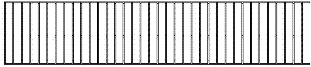
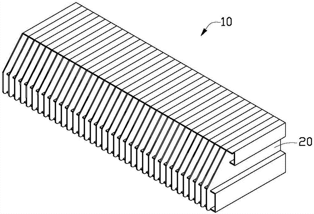
[0017] see figure 2 , shows a perspective view of the heat dissipation device 10 of the present invention, which includes several heat dissipation fins 20 . The heat dissipation device may further include a bottom plate (not shown) carrying heat dissipation fins 20 for contacting corresponding electronic components (not shown) to dissipate heat. The heat dissipation fins 20 abut against each other in parallel along the same direction to form the heat dissipation device 10 .

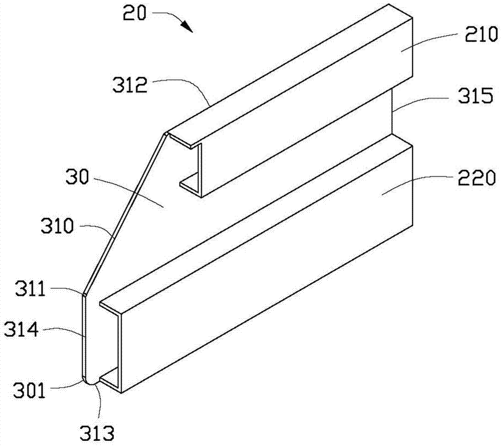
[0018] Please refer to 3-4 again, which shows an enlarged view and a front view of one of the heat dissipation fins 20 of the heat dissipation device 10 . The cooling fin 20 includes a body 30 , an upper flap 210 , and a lower flap 220 . The main body 30 , the upper flap 210 and the lower flap 220 are manufactured separately, and then fixed together by welding or other methods. The body 30 is a pentagonal metal plate, which is roughly a rectangle with one corner cut off. The upper border 312 of the b...


PUM


Abstract

A heat radiator comprises a plurality of heat radiation fins. Each heat radiation fin comprises a body. The surface of the body of each heat radiation fin extends to form a folded plate. The folded plate firstly extends towards the body of each heat radiation fin and then is bent backwards the body. The folded plates are abutted with the adjacent bodies of the heat radiation fins to assemble the heat radiation fins, therefore, heat radiation areas of the heat radiation fins can be enlarged, and function of turbulent flow can be realized. Besides, time of air flow staying among the heat radiation fins can be prolonged, so that convection coefficient of the air flow is increased, and heat transfer effect is improved. Further, the heat radiation fins are more compactly combined due to the fact that the folded plates and the heat radiation fins are abutted, and stability of the heat radiator is improved.

Description

technical field [0001] The invention relates to a cooling device, in particular to a cooling device for cooling electronic products. Background technique [0002] As the processing speed and response frequency of integrated circuit components become faster and higher, more and more heat is generated, and excessive temperature will seriously affect the normal operation of integrated circuits, and even damage the electronic components in them. , so a heat sink is required to cool the integrated circuit. A traditional heat dissipation device usually includes several pieces of heat dissipation fins. The heat dissipation fins dissipate the heat generated by the electronic components through the airflow channels formed between the fins. Such as figure 1 As shown, the traditional heat dissipation fin group is formed by interconnecting several single planar fins. However, due to the small area of ​​the fins, the heat dissipation area of ​​the fin group is small, which is not con...

Claims


Application Information

Patent Timeline
Patent Type & Authority Applications(China)
IPC IPC(8): H05K7/20
Inventor 徐伟杭
Owner FURUI PRECISE COMPONENT (KUNSHAN) CO LTD
Why Eureka
Try Eureka