Tension control device of hot mill and control method

A technology of tension control and hot rolling mill, applied in the direction of tension/pressure control, etc., which can solve the problems of plate width variation and insufficient

Active Publication Date: 2015-01-14
HITACHI LTD
View PDF10 Cites 2 Cited by
  • Summary
  • Abstract
  • Description
  • Claims
  • Application Information

AI Technical Summary

Problems solved by technology

Therefore, the influence of the change in tension on the change in the width of the plate is not sufficiently considered, so there are cases where the width of the plate varies at the front and rear ends of the steel plate and other parts.

Method used


Image

  • Tension control device of hot mill and control method
  • Tension control device of hot mill and control method
  • Tension control device of hot mill and control method

Examples


Embodiment 1

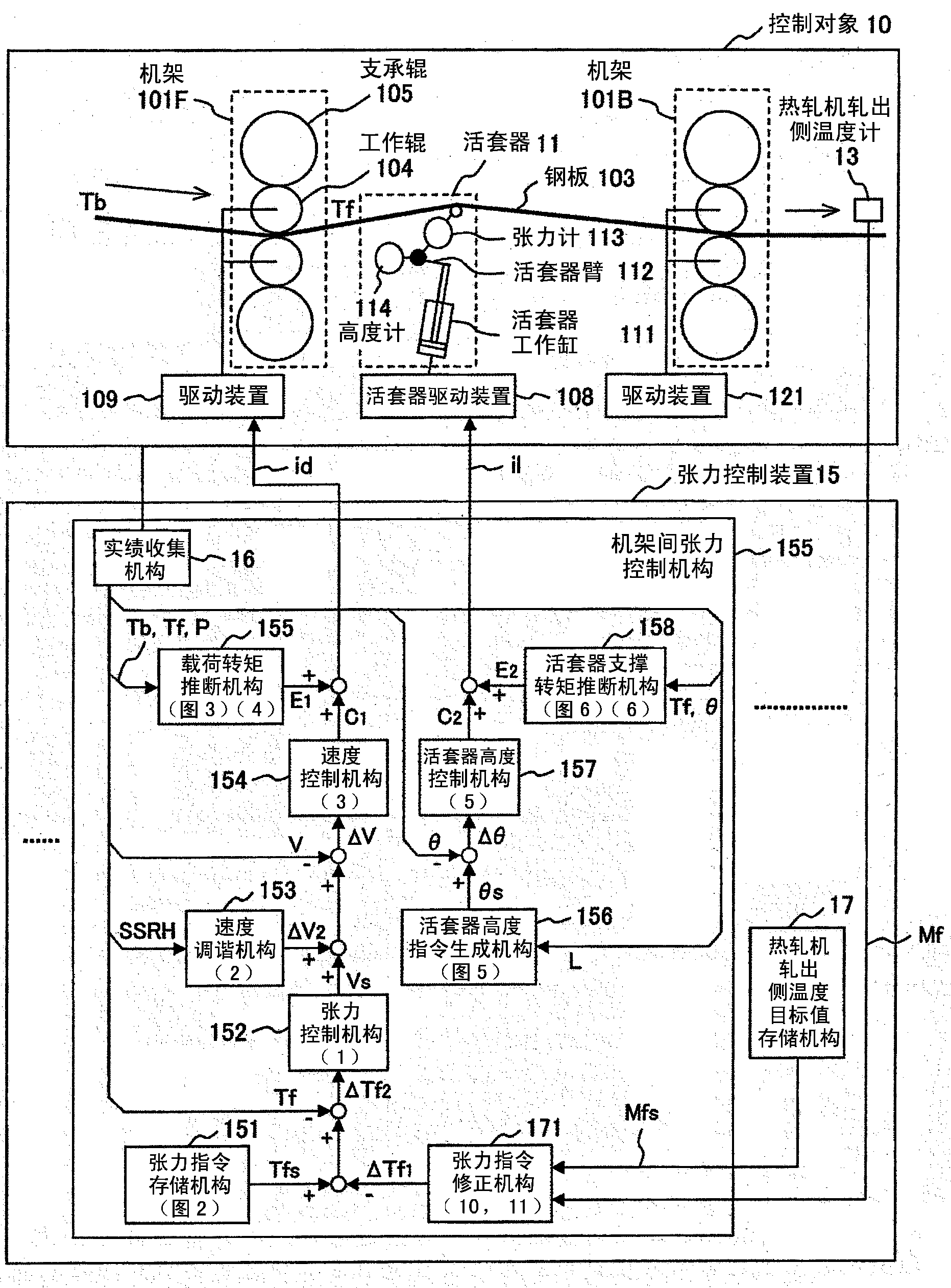
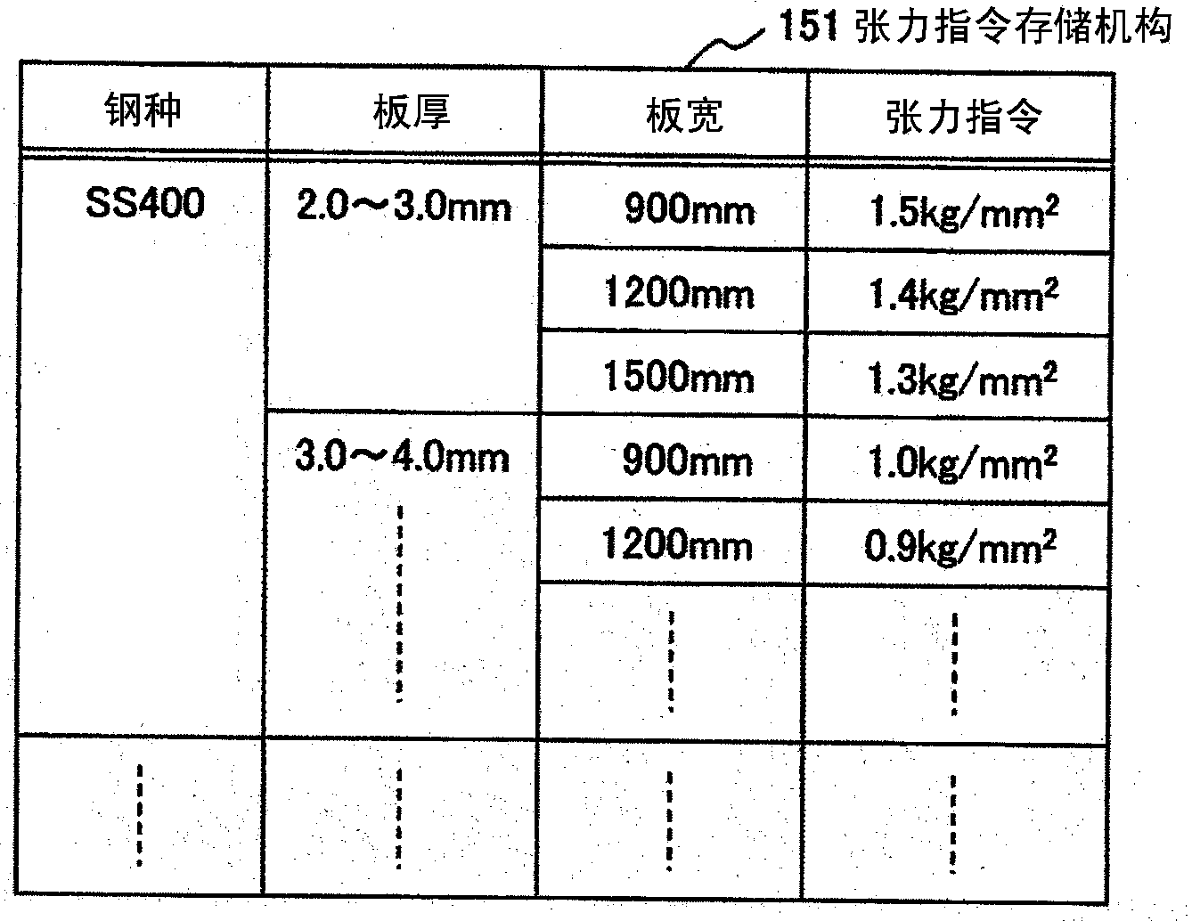
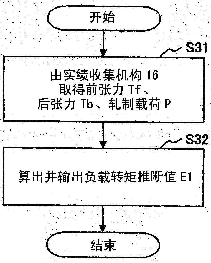
[0070] figure 1 This shows the first embodiment of the present invention. In the tension control of the hot rolling mill of the first embodiment, it is characterized in that correction is made in accordance with the temperature of the rolling side of the hot rolling mill to drive the drive device of the stand. in figure 1 Here, the tension control device 15 receives various signals from the control target 10 (hot rolling mill), and outputs the control signal to the control target 10.

[0071] First, the configuration of the control target 10 will be described. In this embodiment, the control target 10 is a tandem mill that continuously rolls the steel plate 103 with a plurality of stands 101. The steel plate 103 moves from the left side to the right side as shown in the figure, and as it travels from the first stand 101F on the upstream side to the second stand 101B on the downstream side, the steel plate 103 is gradually thinned. In addition, there are actually multiple stands...

Embodiment 2

[0138] Picture 9 This shows the second embodiment of the present invention. in Picture 9 Here, instead of the rolling-out side temperature Mf of the hot rolling mill, the hot rolling-in side temperature Mb is used to calculate the correction value of the tension command, and the driving device as the operating end is driven. Picture 9 In addition to this point, the composition and function of figure 1 Exactly the same.

[0139] Picture 10 The processing performed by the tension command correction mechanism 901 is shown. The tension command correction mechanism 901 first obtains the target value Mb of the temperature on the delivery side of the hot rolling mill from the target temperature storage mechanism 903 on the delivery side of the hot rolling mill in step S101. Although the target value Mbs of the temperature on the feeding side of the hot rolling mill may be fixed, it may be set to a different value depending on the location of the steel sheet.

[0140] Next, in step S1...

Embodiment 3

[0155] Picture 11 This shows the third embodiment of the present invention. in Picture 11 In this method, the correction value of the tension command is calculated using the temperature of the feeding side of the rolling mill and the temperature of the rolling side of the rolling mill, and the driving device as the operating end is driven. Picture 11 The composition and function of the figure 1 Exactly the same.

[0156] Picture 12 The processing performed by the tension command correction mechanism 1101 is shown. The tension command correction mechanism 1101 first, in step S101, acquires the target value Mbs of the temperature on the delivery side of the hot rolling mill from the target temperature storage mechanism 903 on the delivery side of the hot rolling mill. Next, in step S102, the target value Mbf of the hot rolling mill rolling side temperature is acquired from the hot rolling mill rolling side temperature target value storage means 170. Although the target value M...


PUM


Abstract

The invention provides a tension control device of a hot mill and a control method, for reducing the plate width deviation caused by the steel plate temperature effects. By taking a hot mill possessing a plurality of rolling racks and a looper between the racks as a control object, the tension control device of the hot mill for setting the tension of a steel plate passing through the hot mill as a desired value, comprises a tension instruction storing mechanism which stores tension instruction values; a tension instruction correcting mechanism which obtains the detection temperature of a thermometer used for measuring the temperature of the steel plate, and corrects the tension instruction value according to the deviation of the target temperature and the detection temperature of the steel plate; and a tension control mechanism which adjusts the hot mill according to the deviation of the corrected tension instruction value and the detected tension value.

Description

Technical field [0001] The present invention relates to a tension control device for a hot rolling mill and a control method thereof, in particular to a hot rolling which is suitable for stabilizing the tension control of the steel plate between the stands and reducing plate thickness changes or width shrinkage. Machine tension control device and its control method. Background technique [0002] As a prior art for controlling the tension of the steel sheet between stands of a hot rolling mill by focusing on the precision of the width or thickness of the steel sheet, there are the following methods. [0003] Patent Document 1 describes a method of measuring the actual value of the plate width using a plate width gauge provided on the rolling side of the finishing rolling stand, and correcting the tension setting value so that the actual value becomes the target value of the plate width . [0004] Patent Document 2 discloses a control method based on the time series of the measured v...

Claims


Application Information

Patent Timeline
Patent Type & Authority Patents(China)
IPC IPC(8): B21B37/48
Inventor 鹿山昌宏小林拓也
Owner HITACHI LTD
Why Eureka
Try Eureka