Horizontal feeding device of numerical control vertical lathe with maximum machining diameter of 2.5m

A CNC vertical, diameter machining technology, applied in feeding devices, metal processing equipment, metal processing machinery parts, etc., can solve the problems of complexity, high price, difficult maintenance, etc., to improve positioning accuracy and motion accuracy, and low cost of use , the effect of simple structure

Inactive Publication Date: 2012-11-14
中传重型机床有限公司
View PDF5 Cites 2 Cited by
  • Summary
  • Abstract
  • Description
  • Claims
  • Application Information

AI Technical Summary

Problems solved by technology

In the process of CNC transformation of ordinary C5225 products, we found that they generally use the complex, inefficient, and low-precision transmission chain of the old-fashioned structure of the feed box-T-shaped screw, and if the ZF and other reducers are used, although The performance is high, but there are problems such as high price and difficult maintenance. At present, the industry is eager to develop a new product that can not only meet the requirements of use, but also reduce costs and maintenance costs, and the structure is simpler, clearer, and easier to maintain. more convenient
[0003] Although the synchronous toothed belt has reliable transmission and strong impact resistance in the transmission mechanism, because the teeth compounded on the transmission belt are easily damaged during the power transmission process, it is generally used for constant speed or small power transmission with relatively high speed accuracy requirements. In the transmission equipment, at present, this transmission method is used for the increase and decrease transmission system with a relatively large speed ratio, and at the same time, the occasion of a large output power, for example, the reduction ratio is 1:4, and the maximum processing diameter is 2.5 m CNC vertical lathe application, there is no report

Method used


Image

  • Horizontal feeding device of numerical control vertical lathe with maximum machining diameter of 2.5m
  • Horizontal feeding device of numerical control vertical lathe with maximum machining diameter of 2.5m

Examples


Embodiment Construction

[0014] The accompanying drawings disclose the specific structure of the embodiment of the present invention without limitation, and the present invention will be further described below in conjunction with the accompanying drawings

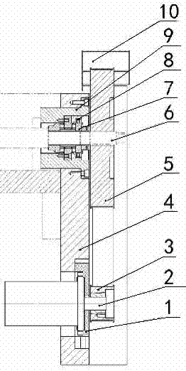
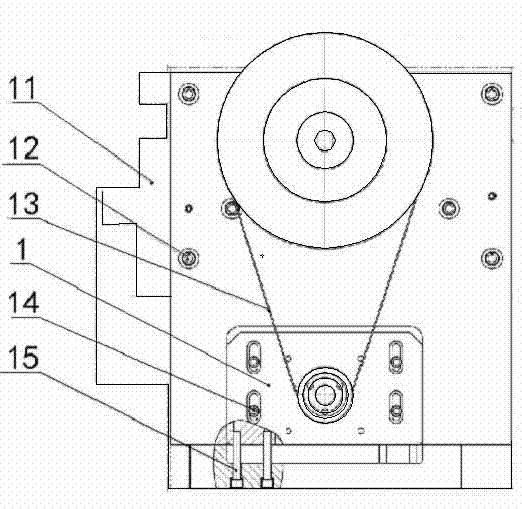
[0015] Depend on figure 1 , 2 It can be seen that the present invention includes a beam 11, a beam end plate 4, a servo motor 2, a synchronous belt transmission device composed of a toothed driving pulley 3, a toothed passive pulley 5 and a synchronous toothed belt 13, and leading parts such as a lead screw 6. composition. The beam end plate 4 is fixed on the end of the beam 11 by screws 12, and the servo motor 2 is installed on the distance-adjusting slide 1; after the servo motor 2 and the distance-adjusting slide 1 are fixed, the distance-adjusting slide 1 is first tightened Screw 15 adjusts the center distance between the motor shaft and the lead screw, and then fixes its position on the beam end plate 4 by locking screw 14; the lead screw 6...


PUM


Abstract

The invention relates to a horizontal feeding device of a numerical control vertical lathe with maximum machining diameter of 2.5m. The device comprises a cross beam, a cross beam end plate, a servo motor and a screw rod, wherein the cross beam end plate is mounted on the end face of the cross beam, and the servo motor and the screw rod are mounted on a same side of the cross beam end plate. The horizontal feeding device is characterized in that the cross beam end plate is provided with a distance adjusting slide seat and a shaft sleeve; the servo motor is fixedly mounted on the cross beam end plate through the distance adjusting slide seat; the screw rod is mounted in the shaft sleeve through a bearing and a driven belt wheel is fixedly arranged at the end part of the screw rod; the servo motor is fixedly connected with a driving belt wheel; the speed reducing ratio of the driving belt wheel to the driven belt wheel is 1: 4 and the central distance between the driving belt wheel and the driven belt wheel is 400-420mm; the driving belt wheel and the driven belt wheel are synchronously connected through a synchronous toothed belt; and at least seven teeth are arranged inside a corner covering region formed by the synchronous toothed belt on the driving belt wheel and are engaged with one another.

Description

technical field [0001] The invention relates to a horizontal feeding device, in particular to a horizontal feeding device of a numerical control vertical lathe with a maximum workpiece diameter of 2.5m. Background technique [0002] The horizontal feed device is the main component of the horizontal (X-axis) feed system of the CNC vertical lathe. As a power transmission unit, it transmits the rotary motion of the servo motor to the ball screw to realize the horizontal linear motion of the tool post. In the process of numerical control transformation of ordinary C5225 products, we found that they generally adopt the complex, inefficient and low-precision transmission chain of the old-fashioned structure of the feed box-T-type screw, and if the reducer such as ZF is used, although The performance is high, but there are problems such as high price and difficult maintenance. At present, the industry is eager to develop a new product that can not only meet the requirements of use,...

Claims


Application Information

Patent Timeline
Patent Type & Authority Applications(China)
IPC IPC(8): B23Q5/40B23Q5/36
Inventor 姬国栋何京丞牛明智
Owner 中传重型机床有限公司
Why Eureka
Try Eureka