Residual resin discharge device of hot-runner injection mold equipment

A technology of hot runner injection molding and discharge device, applied in the field of residual resin discharge device, can solve the problem of increasing the amount of resin, and achieve the effects of cost reduction, simple resin replacement operation, and reduced resin consumption

Active Publication Date: 2012-11-14
哈希斯热流道科技(苏州)有限公司
View PDF6 Cites 6 Cited by
  • Summary
  • Abstract
  • Description
  • Claims
  • Application Information

AI Technical Summary

Problems solved by technology

When the capacity of the cavity in the mold is relatively small compared to the supply of the resin supply device, the amount of resin remaining inside the flow channel of the manifold will increase, and the amount of resin consumed during refueling injection will also increase

Method used


Image

  • Residual resin discharge device of hot-runner injection mold equipment
  • Residual resin discharge device of hot-runner injection mold equipment
  • Residual resin discharge device of hot-runner injection mold equipment

Examples


Embodiment 1

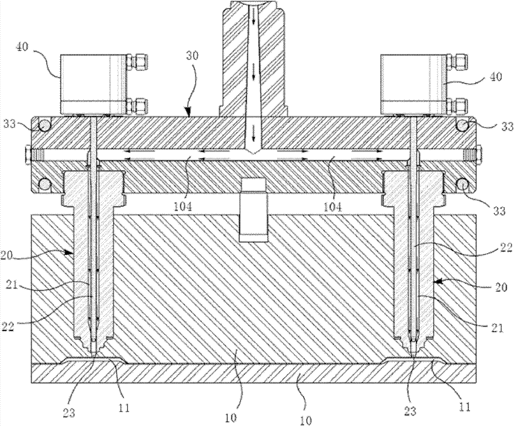
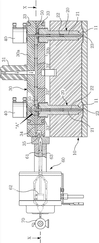
[0061] Figure 2 to Figure 5 It is the first embodiment of the present invention. The hot runner injection mold device of the first embodiment of the present invention includes a mold cavity plate 10 forming more than one cavity 11, a splitter plate 30 forming a plurality of runners 32, a nozzle 20 arranged in the cavity mold plate, and an inner valve for driving the nozzle. The needle 22 reciprocates to open and close the valve needle driving means 40 of the nozzle gate 23 and the molten resin supply means (not shown).

[0062] Such as figure 2 and image 3 As shown, the flow channel of the above splitter plate is composed of a plurality of flow channels 32 branched from the main gate 31, and the flow channels communicate with the resin channel 21 in the nozzle at each front position. When in use, the molten resin supplied by the molten resin supply device enters each flow channel 32 from the main gate 31 above the distributor plate, then flows into the resin channel 21 i...

Embodiment 2

[0077] Figure 6 to Figure 8 is the residual resin discharge device according to the second embodiment of the present invention

[0078] The remaining resin discharge device of the second embodiment is the same as the first embodiment except that the structure of the manifold is integrated and the resin separation and discharge device 50 is embedded in the nozzle coupling hole on the bottom surface of the manifold 30 . The description of the same components and their functions as those of the first embodiment will be omitted below. Also, the same drawing symbols are used for the same parts as those in the first embodiment.

[0079] The resin separating and discharging device 50 of the above second embodiment is as Figure 6 As shown, the nozzle setting hole of the distributor plate is embedded in the coaxial direction with the resin channel 21 of the upper nozzle 20, and the lower end is supported by the upper end of the nozzle provided by screwing. In this installed state,...

Embodiment 3

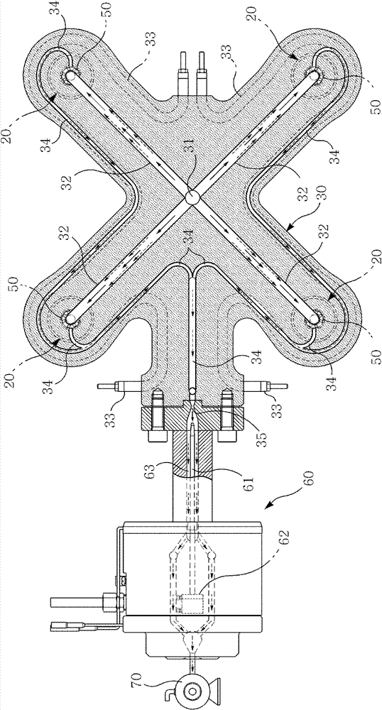
[0084] Figure 9 and Figure 10 is the third embodiment of the present invention. In the third embodiment of the present invention, a plurality of nozzles 20 are provided on the splitter plate 30 of the hot runner injection mold device, and each of the above nozzles 20 is connected with the runner 32 that the main gate 31 divides.

[0085] Each nozzle 20 uses the valve needle 22 raised and lowered by the valve needle driving device to open and close the gate as in other embodiments, and supplies or cuts off the supply of molten resin flowing through the runner 32 to the cavity.

[0086] The multiple nozzles 20 provided on the distributor plate above are formed by combining multiple nozzles, and each nozzle combination is formed by multiple (two in the embodiment) nozzles 20 .

[0087] These multiple nozzle combinations act either simultaneously or individually according to the injection molding process depending on the shape or structure of the injection molded product. In ...


PUM


Abstract

The invention discloses a residual resin discharge device of hot-runner injection mold equipment. According to the invention, resin separation discharge devices are disposed between runners of a splitter plate and resin channels of nozzles for connection, so that residual resin in the runners can be separated into resin discharge channels for discharge. Moreover, separation discharge channels are arranged for connecting the resin channel lower ends of the nozzles and the resin discharge channels on one sides of the nozzles, so that the residual resin on the inner walls of the nozzle resin channels can be discharged into the resin discharge channels through the separation discharge channels. The residual resin discharge device can effectively separate the residual resin in the inner walls of the splitter plate runners and the nozzle resin channels from new resin and discharge, thus avoiding mixing of the residual resin into new melt resin to result in poor molding.

Description

technical field [0001] The invention relates to a residual resin discharge device of a hot runner injection mold device. Background technique [0002] The current hot runner injection mold device such as figure 1 As shown, it includes a splitter plate 30, a mold cavity plate 10 and several nozzles 20, several cavity 11 are formed in the mold cavity plate, the splitter plate is arranged above the mold cavity plate, and several runners 32 are formed inside the splitter plate. Two nozzles are respectively arranged in the cavity plate of the mold, and the gates 23 of the several nozzles are respectively facing one cavity, and a resin channel 21 is arranged in the several nozzles, one end of the resin channel communicates with the flow channel, and the other end communicates with the gate. The mouth is connected, and the molten resin is supplied to each nozzle through the flow channel and the resin channel by the external molten resin supply device, and then supplied to the cavi...

Claims


Application Information

Patent Timeline
Patent Type & Authority Applications(China)
IPC IPC(8): B29C45/27
CPCB29C45/1753B29C45/2725
Inventor 许南旭
Owner 哈希斯热流道科技(苏州)有限公司
Why Eureka
Try Eureka